Power divider

A technology of power divider and power divider, applied in the field of communication, can solve the problems of rising damage rate, high manufacturing cost, poor sealing of the casing, etc., and achieve the effects of convenient use, strong identification and simple structure

Inactive Publication Date: 2017-10-17
江苏凡为通信科技有限公司
View PDF0 Cites 3 Cited by
  • Summary
  • Abstract
  • Description
  • Claims
  • Application Information

AI Technical Summary

Problems solved by technology

[0002] The full name of the power divider is a power divider. It is a device that divides the energy of one input signal into two or more outputs with equal or unequal energy. It can also conversely synthesize the energy of multiple signals into one output. A certain degree of isolation should be guaranteed between the output ports. The existing power splitter has a heavy structure, poor stability of the internal power splitter, and poor sealing of the housing, which leads to a gradual increase in the damage rate and high manufacturing costs.

Method used


Image

  • Power divider
  • Power divider
  • Power divider

Examples


Embodiment Construction

[0020] The implementation of the present application will be described in detail below with reference to the accompanying drawings and examples, so as to fully understand and implement the implementation process of how the present application uses technical means to solve technical problems and achieve technical effects.

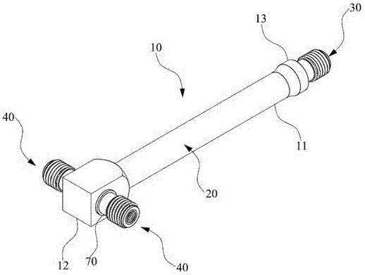
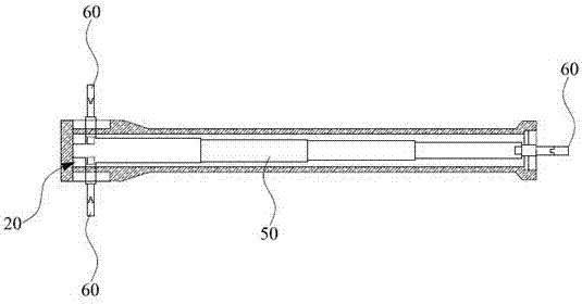
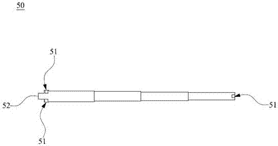
[0021] Please also refer to figure 1 and figure 2 , figure 1 It is a three-dimensional view of the power splitter of the embodiment of the present application; figure 2 It is the internal schematic diagram of the power divider of the embodiment of the present application. As shown in the figure, a power splitter includes a housing 10, the housing 10 includes an incident part 11 and an outgoing part 12, and the housing 10 has a chamber 20 communicating with the incident part 11 and the outgoing part 12; The input interface 30 at one end of 11; the output interface 40 respectively arranged on both sides of the exit part 12; the power distribution rod 50 b...


PUM


Abstract

The application discloses a power splitter, which includes a casing, the casing includes an incident part and an outgoing part, and the casing has a chamber communicating with the incident part and the outgoing part; an input interface arranged at one end of the incident part; The output interface on both sides of the output part; the power distribution rod built in the chamber; and the pins connecting the power distribution rod with the input interface and output interface. The casing of the present invention is provided with an incident part and an outgoing part, which is highly recognizable, convenient to use, and simple in structure; meanwhile, the power distribution rod has a thin rod extension part that interferes with the inner wall of the chamber, thereby improving stability.

Description

technical field [0001] The present application belongs to the technical field of communications, and in particular relates to a power divider. Background technique [0002] The full name of the power divider is a power divider. It is a device that divides the energy of one input signal into two or more outputs with equal or unequal energy. It can also conversely synthesize the energy of multiple signals into one output. A certain degree of isolation should be ensured between the output ports. The existing power splitter has a heavy structure, poor stability of the internal power splitter, and poor sealing of the shell, increasing the damage rate and high manufacturing cost. Contents of the invention [0003] In view of this, the technical problem to be solved in this application is to provide a power splitter, by setting a power splitter rod with a special structure to cooperate with the pins, the stability is improved and the malfunction of the power splitter is avoid...

Claims


Application Information

Patent Timeline
Patent Type & Authority Applications(China)
IPC IPC(8): H01P5/12
CPCH01P5/12
Inventor 郦银海
Owner 江苏凡为通信科技有限公司
Why Eureka
Try Eureka