Welding device

A technology for welding devices and distribution boxes, which is applied to devices with bendable leads, bus/line layout, substation/switch layout details, etc., which can solve potential safety hazards, damage to the insulation of power supply lines, and inconvenient retraction of the length of power supply lines And other issues

Inactive Publication Date: 2017-10-17
何华勇
View PDF1 Cites 1 Cited by
  • Summary
  • Abstract
  • Description
  • Claims
  • Application Information

AI Technical Summary

Problems solved by technology

[0002] At present, electric welding machines are more and more widely used in some electric welding factories. However, due to the relatively short power supply line of the electric welding machine, it often affects the movement of the electric welding machine during welding. In the past, similar phenomena are generally used. One or more terminal boards are lengthened and connected to achieve the purpose of plugging and supplying power to the electric welding machine. However, after multiple terminal boards are connected, the power supply wires have a certain length, which is extremely inconvenient when retracting, and the power supply wires can be easily removed when not in use. Throwing it on the ground not only occupies a large area and affects the appearance, but also is vulnerable to various accidental damages, such as people stepping on it, scratching on hard objects, etc., which will cause damage to the outer insulation of the power supply line and reduce the life of the power supply line. Potential safety hazards. In addition, due to the different powers of welding machines used in welding factories, voltage converters are generally used to meet the power supply requirements of different types of welding machines. However, these converters are generally installed outside and Without any protection measures, easily damaged

Method used


Image

  • Welding device
  • Welding device
  • Welding device

Examples


Embodiment Construction

[0018] All features disclosed in this specification, or steps in all methods or processes disclosed, may be combined in any manner, except for mutually exclusive features and / or steps.

[0019] Any feature disclosed in this specification (including any appended claims, abstract and drawings), unless expressly stated otherwise, may be replaced by alternative features which are equivalent or serve a similar purpose. That is, unless expressly stated otherwise, each feature is one example only of a series of equivalent or similar features.

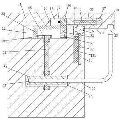
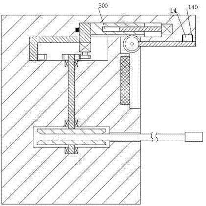
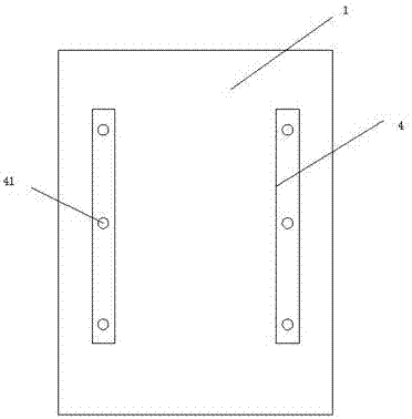
[0020] Such as Figure 1-3 As shown, a welding device of the present invention includes a distribution box 1, the left side of the distribution box 1 is symmetrically provided with fixed rods 4 front and back, and multiple groups of fixed holes 41 are equidistantly provided on the fixed rods 4, The fixing rod 4 is used for fixing the distribution box 1, and the upper right end of the distribution box 1 is provided with a protruding plate 101,...


PUM


Abstract

Provided is a welding device including a distribution box, the upper end of the distribution box is provided with a protruding plate, the distribution box is provided with a receiving groove and a wire hole communicated with the receiving groove, the receiving groove is rotationally provided with a rotary shaft, the rotary shaft is fixedly provided with a receiving rotary tray which is wound with a cable, a first slide groove prolonging into the protruding plate is arranged in the distribution box, a sliding plate is arranged in the first slide groove in a left-right sliding manner, a second slide groove arranged under the first slide groove and communicated with the first slide groove is arranged in the distribution box, a second sliding block is arranged in the second slide groove in a left-right sliding manner, the left end of the sliding plate is fixedly provided with a first sliding block, the lower end of the first sliding block extends into the second slide groove, a connecting rod is fixedly connected between the lower end of the first sliding block and the second sliding block, the lower end of the first sliding block is fixedly provided with a first driving machine, and the first driving machine is provided with a first toothed wheel.

Description

technical field [0001] The invention relates to the field of welding technology, in particular to a welding device. Background technique [0002] At present, electric welding machines are more and more widely used in some electric welding factories. However, due to the relatively short power supply line of the electric welding machine, it often affects the movement of the electric welding machine during welding. In the past, similar phenomena are generally used. One or more terminal boards are lengthened and connected to achieve the purpose of plugging and supplying power to the electric welding machine. However, after multiple terminal boards are connected, the power supply wires have a certain length, which is extremely inconvenient when retracting, and the power supply wires can be easily removed when not in use. Throwing it on the ground not only occupies a large area and affects the appearance, but also is vulnerable to various accidental damages, such as people steppin...

Claims


Application Information

Patent Timeline
Patent Type & Authority Applications(China)
IPC IPC(8): H01R13/72H02G11/02H02B1/46H02B1/20
CPCH01R13/72H02B1/20H02B1/46H02G11/02
Inventor 何华勇
Owner 何华勇
Why Eureka
Try Eureka