Safety power drawer cabinet equipment

A drawer cabinet and electric power technology, which is applied in the direction of pull-out switch cabinets, electrical components, switchgear, etc., can solve the problems of increasing the risk of electric shock for maintenance personnel, inconvenient maintenance of electrical components, and potential safety hazards, so as to avoid the risk of electric shock and facilitate Maintenance and repair, increase the effect of stability

Inactive Publication Date: 2017-10-17
陈玉飞
View PDF7 Cites 1 Cited by
  • Summary
  • Abstract
  • Description
  • Claims
  • Application Information

AI Technical Summary

Problems solved by technology

[0002] The power drawer is an important part of power equipment, mainly used to install electrical components to ensure the normal operation of the electrical components. In order to facilitate the installation of electrical components, the power drawer is usually set in a pull-out manner. The electrical connection mode of the electrical components in the drawer cabinet is basically always powered by plugging. Due to the particularity of the plug-in power supply mode, no matter whether the drawer cabinet is in the pulled out state or the inserted state, the electrical components in the drawer cabinet are always in the state. It is very inconvenient for the maintenance of electrical components. When the drawer cabinet is pulled out for maintenance, the electrical components in it cannot be powered off by themselves, which increases the risk of electric shock for maintenance personnel and poses a greater safety hazard. Hidden danger

Method used


Image

  • Safety power drawer cabinet equipment
  • Safety power drawer cabinet equipment
  • Safety power drawer cabinet equipment

Examples


Embodiment Construction

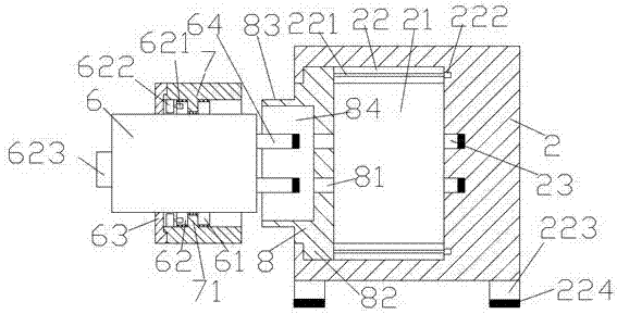
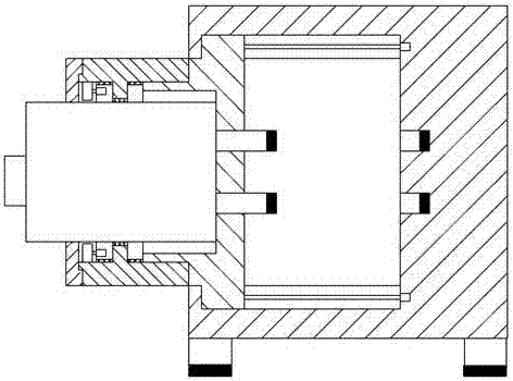
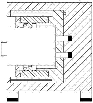
[0021] Such as Figure 1-Figure 5 As shown, a safe power drawer device of the present invention includes a cabinet base 2 and a drawer cabinet 6 arranged on the left side of the cabinet base 2, and a push chamber 21 is provided in the cabinet base 2, and the push chamber 21 The upper and lower sides are oppositely provided with a sliding cavity 22, the sliding cavity 22 is provided with a screw rod 221, the right end of the screw rod 221 is connected with the first motor 222, and the pushing cavity 21 is provided with a sliding Block 8, the upper and lower sides of the sliding block 8 are oppositely provided with a block 82 extending into the sliding cavity 22, the block 82 is threadedly connected with the screw rod 221, and the sliding The left side of the moving block 8 is provided with an external thread connecting portion 83, and the external thread connecting portion 83 is provided with a push groove 84, and the sliding block 8 on the right side of the push groove 84 is p...


PUM


Abstract

The invention discloses safety power drawer cabinet equipment, and the equipment comprises a cabinet seat and a drawer cabinet disposed at the left side of the cabinet seat. The interior of the cabinet seat is provided with a push cavity, and the upper and lower sides of the push cavity are oppositely provided with sliding cavities. The interior of each sliding cavity is provided with a spiral rod, and the right side end of the spiral rod is connected with a first motor. The interior of the push cavity is provided with a sliding block, and the upper and lower sides of the sliding block are oppositely provided with stopping blocks stretching into the sliding cavities. The stopping blocks and the spiral rod are in screw-thread fit connection with each other. The left side of the sliding block is provided with an external thread connecting part, and the interior of the external thread connecting part is provided with a push groove. The interior of the sliding block at the right side of the push groove is provided with a passing-through hole, and the inner wall, opposite to the right side of the passing-through hole, of the cabinet seat is provided with a piece insertion hole. The push groove is opposite to the drawer cabinet. The equipment is simple in structure, is convenient to operate, is high in safety, is more stable in power supply connection, and effectively avoids the electric shock danger caused when a maintainer touches the piece insertion hole.

Description

technical field [0001] The invention relates to the technical field of electric equipment, in particular to a safe electric drawer cabinet equipment. Background technique [0002] The power drawer is an important part of power equipment, mainly used to install electrical components to ensure the normal operation of the electrical components. In order to facilitate the installation of electrical components, the power drawer is usually set in a pull-out manner. The electrical connection mode of the electrical components in the drawer cabinet is basically always powered by plugging. Due to the particularity of the plug-in power supply mode, no matter whether the drawer cabinet is in the pulled out state or the inserted state, the electrical components in the drawer cabinet are always in the state. It is very inconvenient for the maintenance of electrical components. When the drawer cabinet is pulled out for maintenance, the electrical components in it cannot be powered off by t...

Claims


Application Information

Patent Timeline
IPC IPC(8): H02B11/02H02B11/127H02B11/173
CPCH02B11/02H02B11/127H02B11/173
Inventor 陈玉飞
Owner 陈玉飞
Why Eureka
Try Eureka