Mechanical dragging cutting equipment

A technology of cutting equipment and mechanical traction, applied in metal processing equipment, metal processing mechanical parts, clamping and other directions, can solve the problem of inconvenient continuous production of cutting equipment

Inactive Publication Date: 2017-10-20
HEFEI YAOSHI TONGHUI TECH CO LTD
View PDF0 Cites 6 Cited by
  • Summary
  • Abstract
  • Description
  • Claims
  • Application Information

AI Technical Summary

Problems solved by technology

[0003] The purpose of the present invention is to solve the problem that the cutting equipment in the pr

Method used


Image

  • Mechanical dragging cutting equipment
  • Mechanical dragging cutting equipment

Examples


Embodiment Construction

[0015] The technical solutions in the embodiments of the present invention will be clearly and completely described below with reference to the accompanying drawings in the embodiments of the present invention. Obviously, the described embodiments are only a part of the embodiments of the present invention, but not all of the embodiments.

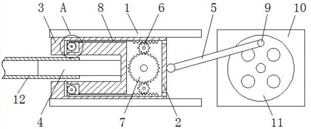
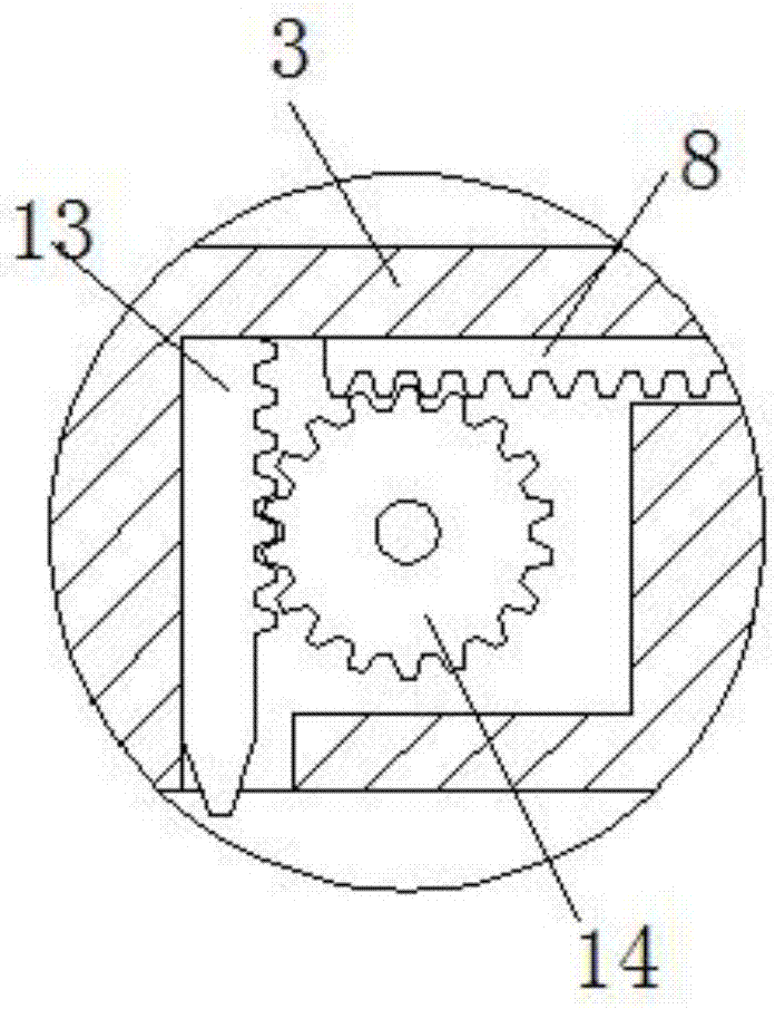
[0016] refer to Figure 1-2 , a mechanical traction cutting equipment, including a chute 1, the bottom end of the chute 1 is provided with a support frame, and the support frame is fixed on the workshop floor, one side of the chute 1 is provided with an intermittent motor 10, and the intermittent type The motor 10 is also installed on the support frame, a sliding installation box 2 is arranged inside the chute 1, a turntable 11 is installed on the driving end of the intermittent motor 10, and a rotating rod 9 is installed on the end of the side wall of the turntable 11 away from the center of the circle, A connecting rod 5 is rotatably conn...


PUM


Abstract

The invention discloses a mechanical traction cutting device, comprising a chute, the bottom end of the chute is provided with a support frame, and the support frame is fixedly arranged on the workshop floor, and an intermittent motor is provided on one side of the chute. And the intermittent motor is also installed on the support frame, the inside of the chute is provided with a sliding installation box, the driving end of the intermittent motor is equipped with a turntable, and the end of the side wall of the turntable away from the center of the circle is equipped with a rotating The side wall of the sliding installation box close to the intermittent motor side is rotatably connected with a connecting rod, and the connecting rod is rotatably connected with the rotating rod, and the side wall of the sliding installation box far away from the intermittent motor is symmetrically installed with There are two fixing seats, and an installation cavity is opened inside the sliding installation box. The invention has exquisite structure, is easy to operate, and skillfully realizes the traction type continuous cutting of the workpiece, avoids the interference between the workpiece and the driving mechanism, and will significantly improve the efficiency of the cutting work.

Description

technical field [0001] The invention relates to the technical field of cutting equipment, in particular to a mechanical traction cutting equipment. Background technique [0002] Cutting is a physical action. In a narrow sense, cutting refers to cutting objects (such as food, wood and other low-hardness objects) with sharp tools such as knives. In a broad sense, cutting refers to using tools, such as machine tools, flames, etc. Objects break apart under pressure or heat. In mathematics, there is also an extended "cutting line", which refers to a straight line that can divide a plane into several parts. Cutting plays an important role in people's production and life. In-line cutting is the most common processing method in cutting processing. Most of the cutting equipment in the prior art pushes the workpiece to the cutting knife for cutting through a dedicated pushing mechanism, which is not convenient for continuous production, and the workpiece is easy to interfere with the...

Claims


Application Information

Patent Timeline
IPC IPC(8): B23Q3/00B23Q7/02B23Q7/00
CPCB23Q3/00B23Q7/00B23Q7/02
Inventor 顾运辉顾明东姚其林
Owner HEFEI YAOSHI TONGHUI TECH CO LTD
Why Eureka
Try Eureka