[0044] In order to better understand the technical content of the present invention, specific embodiments are given together with the attached drawings for description as follows.
[0045] Aspects of the invention are described in this disclosure with reference to the accompanying drawings, which show a number of illustrated embodiments. Embodiments of the present disclosure are not necessarily intended to include all aspects of the invention. It should be appreciated that the various concepts and embodiments described above, as well as those described in more detail below, can be implemented in any of numerous ways, since the concepts and embodiments disclosed herein are not limited to any implementation. In addition, some aspects of the present disclosure may be used alone or in any suitable combination with other aspects of the present disclosure.
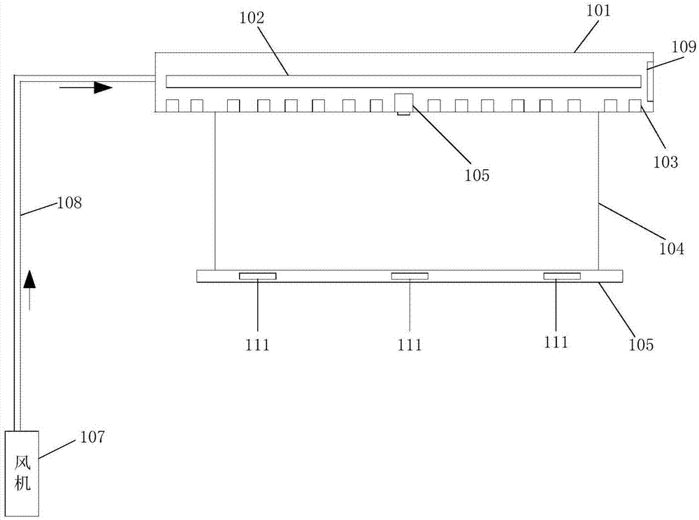
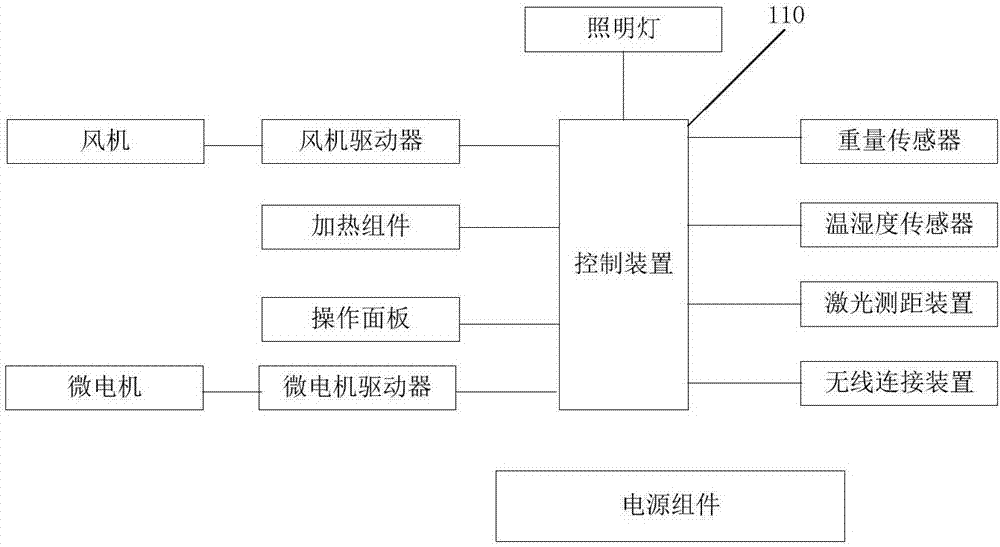
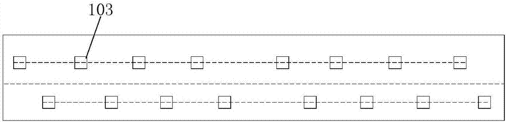
[0046] to combine Figure 1-Figure 4As shown, according to the disclosure of the present invention, an intelligent clothes drying device is proposed, including: a support box 101 containing a power drive assembly and a transmission assembly, and the support box 101 is set to be fixed on the top wall of the balcony; the drive assembly includes two Two micro-motors are respectively located at the two ends of the support box; the transmission assembly includes a reduction mechanism connected to the output shaft of the micro-motor and two rollers connected to the output end of the reduction mechanism, and the rollers are controlled and synchronized by the micro-motor Rotate; Traction rope 104, and its one end is around roller and tightens up or elongates along with the rotation of roller; Main drying rod 105, is structured as longitudinal strip, and the other end of traction rope 104 is connected to two ends of main drying rod end, driving the vertical lifting action of the main drying rod 105; the control device 110, connected with the control panel or remote controller, is set to control the operation of the intelligent clothes drying device according to the operation instructions sent by the control panel or remote controller; the fan 107 and the fan driver , the fan driver is connected to the control device 110, and is set to control the operation of the fan by the control device; the ventilation pipeline 108, one end of which is connected to the fan 107, and the other end is connected to the blowing pipeline provided in the support box 101, so that the fan exhaust The air sent enters the blowing pipeline in the support box after being pressurized, and the direction of the outlet of the blowing pipeline is towards the main drying rod; the heating assembly 102 is connected with the control device 110 and is set to generate heat according to the control of the control device.
[0047] In the embodiment of the present invention, the two ends of the support box 101 are closed, and a plurality of air outlets 103 are arranged on the bottom of the support box 101 toward the main drying rod 105, the outlets of the air blowing pipeline correspond to the air outlets 103 one by one, and the heating assembly 102 It is located between the one-to-one corresponding outlet and the air outlet.
[0048] The inside of main drying rod 105 is evenly provided with at least two weight sensors 111 ( figure 1 There are 3 weight sensors in the middle), which are used to monitor the weight change of the main drying pole, and the weight sensors are connected with the control device and transmit weight signals.
[0049] The middle position of the bottom of the support box 101 towards the direction of the main airing pole is also provided with a laser distance measuring assembly 105. It is connected with the control device 110 and transmits the altitude signal.
[0050] The support box 101 is also provided with a temperature and humidity sensor 109 connected to the control device 110 for monitoring the temperature and humidity of the environment where the intelligent clothes drying device is located.
[0051] A filter screen is also provided at the air outlet 103 of the support box 101 .
[0052] In some embodiments, the heating component 102 includes a hollow substrate and a plurality of PTC heating components disposed on the hollow substrate.
[0053] Alternatively, the heating assembly 102 includes a grid heating assembly formed by cross-arranging heating wires.
[0054] Alternatively, the heating assembly 102 includes a mesh heating assembly formed by interweaving glass fibers and carbon fibers.
[0055] By adopting the above scheme, when the wind blown in by the fan passes through the heating component 102, it can be heated and passed through the hollow structure and the grid structure smoothly, and enters the blowing port 103, so as to be blown out to the main airing rod, thus achieving drying. The purpose of drying clothes on the main drying rod.
[0056] Preferably, the intelligent clothes-drying device also includes a wireless connection device connected to the control device for connecting the intelligent clothes-drying device to the network to receive operation instructions through the network. command to control whether it enters the general mode or the drying mode.
[0057] Preferably, as image 3 As shown, the positions of the air outlets 103 are arranged in two straight lines, and the straight lines are parallel to the longitudinal centerline of the support box, wherein the positions of the adjacent air outlets 103 are located in different linear arrangements.
[0058] Further, such as Figure 4 , the positions of the air outlets are arranged in a special shape, and they are arranged on both sides of the support box on the basis of the center line in the longitudinal direction of the support box.
[0059] In this way, using such an arrangement of blowing outlets, hot air or natural air can be conveniently blown to different surfaces of clothes, so that double-row or special-shaped designs can be used to achieve efficient drying.
[0060] In some optional examples, the supporting box 101 is provided with a lighting lamp, which is connected with the control device and used to provide lighting for the intelligent clothes drying device.
[0061] It should be understood that the aforementioned remote controller, or control panel, is a control terminal that cooperates with or is used in conjunction with the control device, especially for users to operate and input instructions to complete the lifting of the main drying pole, heating mode, general blowing mode, lighting mode, etc. Different usage requirements commands.
[0062] combine figure 1 , figure 2 As shown, a kind of intelligent clothes-drying processing method based on above-mentioned smart clothes-drying device, comprises:
[0063] After the clothes are hung on the main drying pole, monitor the weight change of the main drying pole 105, and transmit the weight information of the monitoring result to the control device 110;
[0064] Monitor the distance between the main drying pole 105 and the support box 101;
[0065] Monitor the temperature and humidity of the environment where the smart clothes drying device is located;
[0066] Judging whether to enter the drying mode according to the control panel or the control command from the remote controller, if so, then judging whether to enter the drying mode, controlling the starting blower fan 107 to operate, the heating assembly 102 to operate, and blowing out the heated air to the main drying rod 105 Dry the clothes; if not, enter the general mode, control and start the fan to run, and blow natural air to the main drying rod.
[0067] In a further embodiment, in the drying mode, the control device controls the operation of the fan and the heating assembly according to the distance monitoring results and weight monitoring results:
[0068] Taking the original weight of the main drying rod as the reference benchmark, the weight after the measured clothes are hung on the main drying rod and kept for a predetermined time is a variable, and the difference W0 between the above variable and the reference standard is obtained; when the difference W0 is greater than 0 and When the distance measurement value is greater than the set first threshold L0, the fan is controlled to start running at a predetermined minimum operating speed; when the distance measurement value is greater than the set first threshold L0, the fan is operated at an increased operating speed;
[0069] After the fan is running, control and start the heating component for heating;
[0070] When the weight of the continuously monitored main drying pole changes, the weight change difference W1 within the set collection period T range is obtained. When the amount of W1 is on a downward trend, the operating speed of the fan is controlled to be reduced, and when W1 is less than or equal to 0 , the control turns off the heating element;
[0071] After turning off the heating element, the fan continues to run for the set time and then turns off.
[0072] Although the present invention has been disclosed above with preferred embodiments, it is not intended to limit the present invention. Those skilled in the art of the present invention can make various changes and modifications without departing from the spirit and scope of the present invention. Therefore, the scope of protection of the present invention should be defined by the claims.