Advancing compensation type cable-stayed bridge overall cable-replacement equipment and cable-replacement method using equipment

A cable-stayed bridge and compensation technology, which is applied in the direction of cable-stayed bridges, bridges, bridge parts, etc., can solve the problems of increased tensile stress of the main girder, increased cracking, damage, etc., and achieve the effect of improving safety and avoiding diseases

Pending Publication Date: 2017-10-20
CCCC HIGHWAY CONSULTANTS
View PDF0 Cites 0 Cited by
  • Summary
  • Abstract
  • Description
  • Claims
  • Application Information

AI Technical Summary

Problems solved by technology

[0005] The disadvantage of this method is that long-term closure or restricted traffic will bring adverse social and economic impacts; at the same time, the main girder in this area is in a state of no cable support when the cable is unloaded, because the compressive stress reserve of the old bridge after many years of operation is no longer accurate. It is known that cable replacement will increase the local tensile stress of the main girder and increase the risk of cracking, and even cause irreversible serious damage. It is not suitable for cable replacement in areas with small compressive stress reserves or long cable areas.

Method used


Image

  • Advancing compensation type cable-stayed bridge overall cable-replacement equipment and cable-replacement method using equipment
  • Advancing compensation type cable-stayed bridge overall cable-replacement equipment and cable-replacement method using equipment
  • Advancing compensation type cable-stayed bridge overall cable-replacement equipment and cable-replacement method using equipment

Examples


example 1

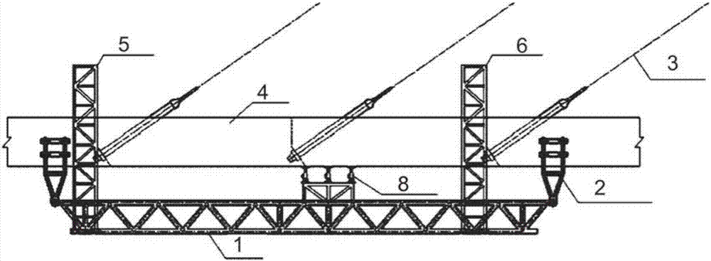
[0065] A concrete cable-stayed bridge with double-sided rib girders as the main girder has a bridge width of 23 meters, a girder height of 2 meters, and a distance of 8 m between the cables on the girder. The stay cables are anchored to the double-sided main girders.

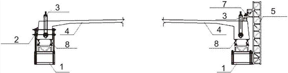
[0066] Assemble the longitudinal track and traction system on the bridge deck, install the vertical ladder, the main truss, and the fixing device for the main girder, and install jacking jacks on the main truss. The main truss is fixed on the vertical ladder in advance; the double-ribbed concrete main girder is horizontally opened and its internal prestressed pipe is avoided, the tie rod of the fixing device is pierced, and the tension screw is fixed, and the weight of the main truss is transferred from the ladder to the fixed device.

[0067] When starting to replace the cables, first touch the anchor head of the tension end of the cable to be replaced to obtain the initial tension; the old cables are unloaded ...

example 2

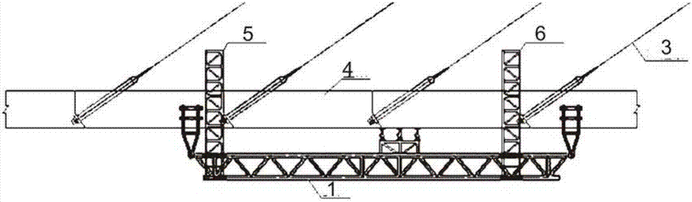
[0070] For a concrete cable-stayed bridge with a single-box multi-chamber closed box girder as the main girder, the stay cables are anchored to the solid block of the side box, and jacking jacks are arranged after the bottom of the side box girder is leveled. The rest of the cable replacement process is the same as in Example 1.

example 3

[0072] For a concrete cable-stayed bridge with a single-box multi-chamber closed box girder as the main girder, the cable-stayed cables are anchored in the middle box. Jacking jacks are arranged in the mid-span of the channel, and the rest of the rope replacement process is the same as that of the example.

[0073] Using the equipment and method of the present invention for cable replacement can synchronously compensate and increase the compressive stress at the bottom of the concrete beam in the cable replacement area, avoiding damage to the bottom edge of the cable replacement process due to tensile stress, improving safety, and ensuring that no damage is caused. It is possible to replace the stay cables or long cables in areas with small compressive stress reserves of concrete cable-stayed bridges while carrying traffic. And the equipment process of the present invention is simple, is easy to operate, and cost is low, that is, the working platform is also a cable unloading ...


PUM


Abstract

The invention discloses advancing compensation type cable-stayed bridge overall cable-replacement equipment and a cable-replacement method using the equipment. The equipment comprises an advancing system and a supporting compensation system; the supporting compensation system comprises a main truss, a main beam fixing device arranged on the main truss and a cable dismounting compensation device arranged on the main truss; and the advancing system comprises a fixed vertical crawling ladder, a movable vertical crawling ladder and a traction braking system. The method comprises the steps that (1) the supporting compensation system is moved to the position where cables need to be replaced; (2) the supporting compensation system and a main beam with the to-be-replaced cables are fixed; (3) cable replacement is implemented, and in the old cable graded cable-dismounting process, cable dismounting force is synchronously compensated through the cable dismounting compensation device; (4) fixing is removed; and (5) the steps are repeated till all the cables are replaced. According to the cable-replacement equipment, in cable replacement, base pressure stress of a concrete beam of a cable-replacement area is synchronously compensated and increased, the phenomenon that in the cable-replacement process, due to tensile stress, diseases occur to bottom edges is avoided, the safety degree is increased, and it is possible that the pull cables or the long cables in the area where cable-stayed bridge pressure reserve is small are replaced while traffic carrying is not affected.

Description

technical field [0001] The invention relates to the field of civil engineering bridges, in particular to the reinforcement and reconstruction of old bridges, and in particular to an integral cable replacement equipment for a traveling compensation type cable-stayed bridge and a cable replacement method using the equipment. Background technique [0002] Since the 1980s, with the development of engineering technology, a large number of concrete cable-stayed bridges have been built and put into use. Among them, the cable-stayed cables in the construction of cable-stayed bridges have a certain service life. The current "Technical Standards for Highway Engineering" stipulates that the design service life of cable-stayed cables is 20 years. In actual use, the service life of cable-stayed cables is between 15 and In 50 years, compared to the bridge's 100-year service life, each cable-stayed bridge needs to be replaced once or more times. [0003] At present, the common stay cables...

Claims


Application Information

Patent Timeline
IPC IPC(8): E01D22/00E01D11/04E01D19/16
CPCE01D11/04E01D19/16E01D22/00
Inventor 董萌李准华崔冰汪信和王国民金小平张万胜
Owner CCCC HIGHWAY CONSULTANTS
Why Eureka
Try Eureka