Shoe Air Cushion Device

An air cushion and gas technology, applied in footwear, soles, clothing, etc., can solve problems such as plantar fasciitis, foot fatigue and soreness, and achieve the effect of comfort and decompression

Active Publication Date: 2019-11-26
欣合信股ふん
View PDF6 Cites 0 Cited by
  • Summary
  • Abstract
  • Description
  • Claims
  • Application Information

AI Technical Summary

Problems solved by technology

However, the pressure and impact brought by standing, walking, and running for a long time have accumulated on people's feet, which may lead to fatigue and soreness of the feet, and more seriously, may cause plantar tendon damage. Membranitis and easy to cause knee joints, shoulder pain, etc. Therefore, many companies on the market have successively developed shoes with different functions to provide people with comfortable wearing shoes. The safety and stability are nothing more than shoes with air cushions, and air cushions are a kind of airbag filled with compressed gas placed on the sole part of the shoe. The airbag is like a balloon full of air, which can absorb shocks and is not easy to break or crush. It can also provide additional shock absorption and support; in order to cooperate with different sports actions or reduce the shock caused by the impact of the ankle and the ground during daily walking, the size and placement of the airbags are also different, usually between the heel and the forefoot The lower part of the foot is relatively stressed, so it is necessary to match the air cushion at its stressed position as a support to block the momentum generated by the heel and forefoot during walking and sports movements and the ground

Method used


Image

  • Shoe Air Cushion Device
  • Shoe Air Cushion Device
  • Shoe Air Cushion Device

Examples


Embodiment Construction

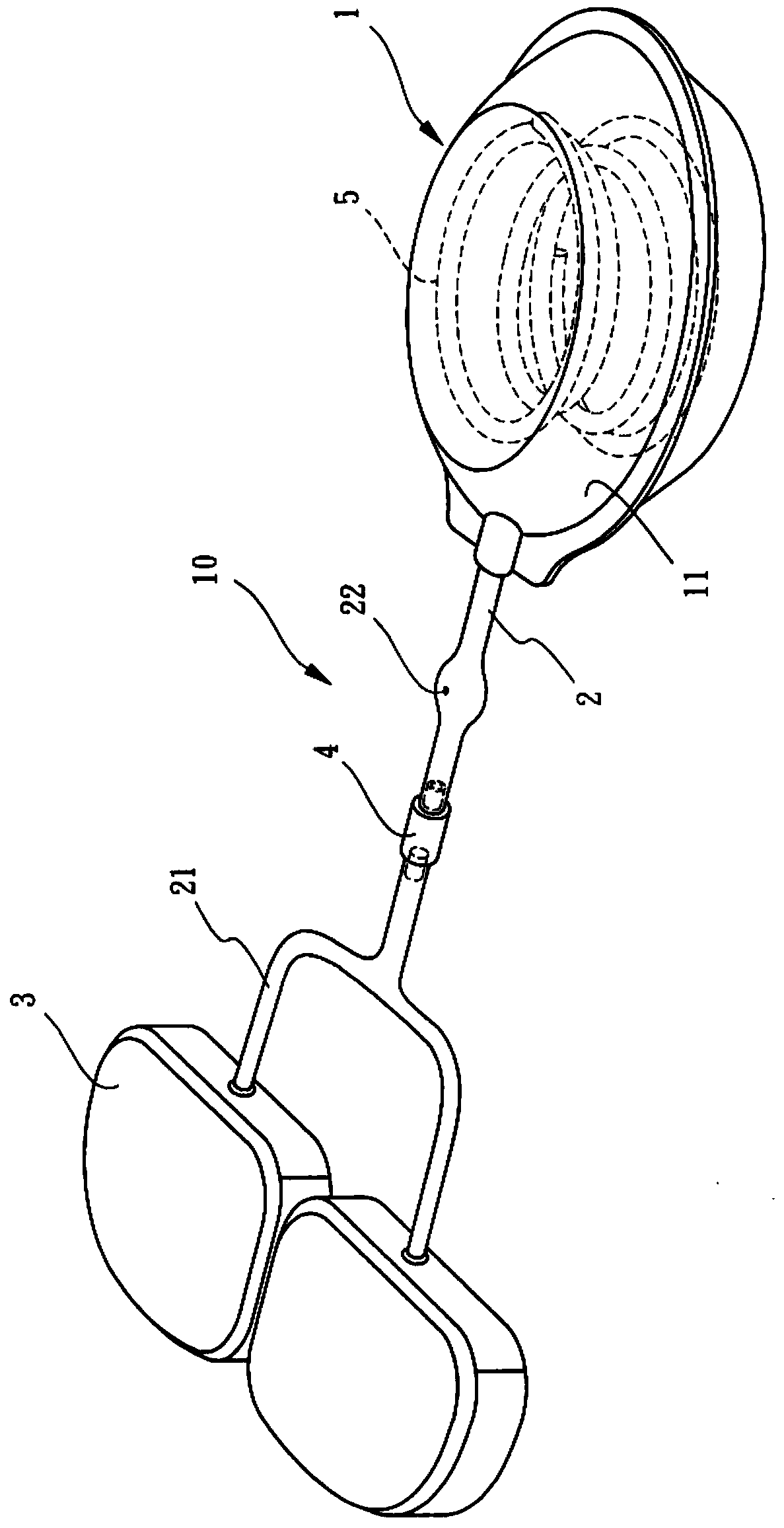
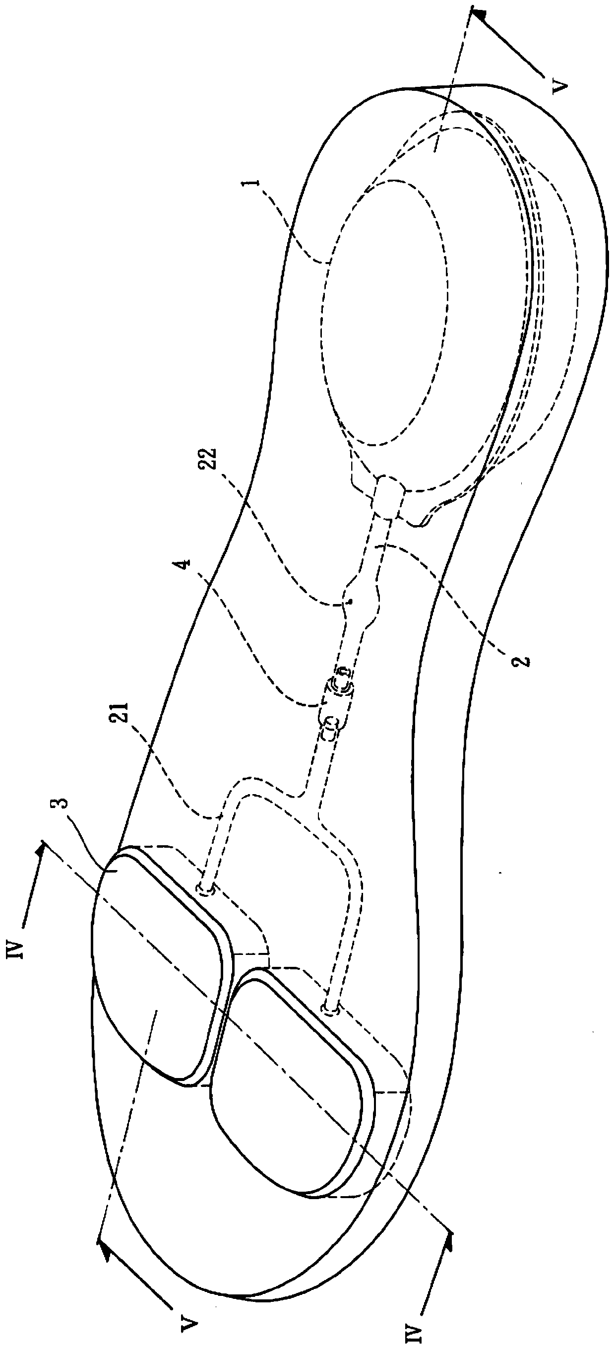
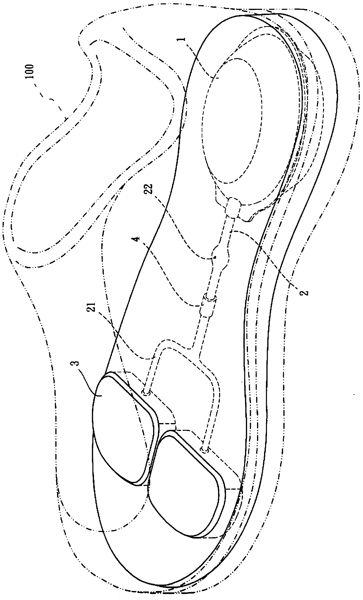
[0027] see Figure 1 to Figure 7 As shown, the figure shows a shoe air cushion device for being installed in a shoe 100, which includes an air cushion device 10, wherein: the air cushion device 10 includes a rear pressure part 1, a conduit 2 and several airbags 3, and One end of the conduit 2 communicates with the rear pressure portion 1, and the other end of the conduit 2 has several branch pipes 21 corresponding to the number of airbags 3, and each branch pipe 21 is connected with each airbag 3 respectively. 2 and the branch pipe 21 is provided with a one-way valve 4, so that the gas flowing from the back pressure part 1 to the air bag 3 will not flow back, and the conduit 2 is provided with an air hole 22 between the back pressure part 1 and the one-way valve 4 for Provide external air to enter the conduit 2 through the air hole 22, and then flow to the back pressure part 1 to fill the gas in the back pressure part 1, and when the back pressure part 1 is forced down, the ga...


PUM


Abstract

A shoe air cushion device is used for being installed in a shoe. The shoe air cushion device comprises an air cushion device. The air cushion device comprises a backward pressing part, a guide pipe and multiple air bags. One end of the guide pipe is communicated with the backward pressing part, the other end of the guide pipe is provided with multiple branch pipes with the number corresponding to that of the air bags, the branch pipes are communicated with the air bags respectively, a one-way valve is arranged between the guide pipe and the branch pipes, and therefore air flowing from the backward pressing part to the air bags cannot flow back. An air hole is formed at the position, between the backward pressing part and the one-way valve, of the guide pipe, external air enters the guide pipe from the air hole and then flows to the backward pressing part in order to fill in the air in the backward pressing part, when the backward pressing part is pressed downwards after bearing force, the air in the backward pressing part is extruded to flow to the branch pipes from the guide pipe through the one-way valve and then flow to the air bags, the air in the air bags is filled to a saturated state, and therefore impact generated between the feet and the ground is relieved.

Description

technical field [0001] The present invention relates to a shoe air-cushion device, in particular to a device that provides the wearer with the ability to step on the air-cushion during foot movements such as walking and jumping, so that the air-cushion has the best compression elasticity, allowing the wearer's foot The upper part has the most comfortable decompression effect. Background technique [0002] Human history began when people were able to stand and walk on two legs. The biggest difference between humans and animals is that humans use their ankles to land on the ground, while animals mostly use palm joints for support. Therefore, the foot is one of the most complex and important structures of the human body. It is composed of 26 bones, 57 movable or micro-movable joints, 108 ligaments and 32 muscles, and forms three vertical and horizontal arches and a pseudo-small horizontal arch. Bows are complexly combined with each other to provide extremely high stability and...

Claims


Application Information

Patent Timeline
Patent Type & Authority Patents(China)
IPC IPC(8): A43B13/20
CPCA43B13/203
Inventor 罗枝芳
Owner 欣合信股ふん
Why Eureka
Try Eureka