
Steel bending device

A steel and bending technology, applied in the field of steel equipment, can solve the problems of low product quality qualification rate, inability to guarantee consistent bending, low efficiency, etc., and achieve the effect of maintaining consistent bending

Inactive Publication Date: 2017-10-24
不二新材料科技有限公司
View PDF6 Cites 1 Cited by
  • Summary
  • Abstract
  • Description
  • Claims
  • Application Information

AI Technical Summary

Problems solved by technology

[0002] In the past, steel was mostly bent by hand, which was not only inefficient, but also the degree of bending could not be guaranteed to be consistent, resulting in a low pass rate of product quality

Method used


Image

  • Steel bending device
  • Steel bending device

Examples


Embodiment Construction

[0010] In order to deepen the understanding of the present invention, the present invention will be further described below in conjunction with the embodiments and accompanying drawings. The embodiments are only used to explain the present invention and do not constitute a limitation to the protection scope of the present invention.

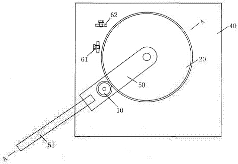
[0011] Such as figure 1 , figure 2 It shows an embodiment of a bending steel device of the present invention, including a workbench 40, a driven wheel 20, a driving wheel 10, and a positioning mechanism are arranged above the workbench 40, and the center of the driven wheel 20 is movably connected to a connecting rod 50 through an axis a , the shaft a runs through the connecting rod 50, the driven wheel 20 and the workbench 40 in sequence, and the center of the driving wheel 10 is connected to the connecting rod 50 through the shaft b, and the shaft b runs through the connecting rod 50 and the driving wheel 10 in turn. The driving wheel 20 is m...


PUM


Abstract

The invention discloses a bending steel device, which includes a workbench. A driven wheel, a driving wheel and a positioning mechanism are arranged above the workbench. The center of the driven wheel is movably connected to a connecting rod through a shaft a, and the shaft a runs through the connecting rod, the driven wheel and the The workbench is set, the center of the driving wheel is connected to the connecting rod through the shaft b, the shaft b runs through the connecting rod and the driving wheel in turn, the driving wheel and the driven wheel are meshed, and the end of the connecting rod far away from the driven wheel is connected with a rotating handle, and the driving wheel and A channel for allowing the workpiece to pass is provided between the driven wheels; the positioning mechanism includes a horizontal positioning piece a and a vertical positioning piece b, and the positioning piece a and the positioning piece b are arranged on the periphery of the driven wheel. The invention has the advantages of simple structure and guaranteed product qualified rate.

Description

Technical field: [0001] The invention relates to the field of steel equipment, in particular to a bending steel device. Background technique: [0002] In the past, steel was mostly bent by hand, which was not only inefficient, but also the degree of bending could not be guaranteed to be consistent, resulting in a low pass rate of product quality. Invention content: [0003] The purpose of the present invention is to overcome the above disadvantages and provide a bending steel device with simple structure and guaranteed product pass rate. [0004] The purpose of the present invention is achieved through the following technical solutions: a bending steel device, including a workbench, a driven wheel, a driving wheel and a positioning mechanism are arranged above the workbench, and the center of the driven wheel is movably connected with a connecting rod through the axis a, and the axis a Set through the connecting rod, driven wheel and workbench in turn, the center of the d...

Claims


Application Information

Patent Timeline
Patent Type & Authority Applications(China)
IPC IPC(8): B21D7/04
CPCB21D7/04
Inventor 耿晓滨
Owner 不二新材料科技有限公司
Learn More