

Rail clamp and its rail car
一种卡轨器、卡件的技术,应用在轨道触轨元件、制动元件与轨道相互作用的制动器、制动器类型等方向,能够解决不适合采矿区使用、车辆不适合等问题,达到使用灵活、使用寿命长、方便安装的效果
- Summary
- Abstract
- Description
- Claims
- Application Information
AI Technical Summary
Problems solved by technology
Method used
Image

Examples
Embodiment 1
[0043] (Embodiment 1, one of rail car)
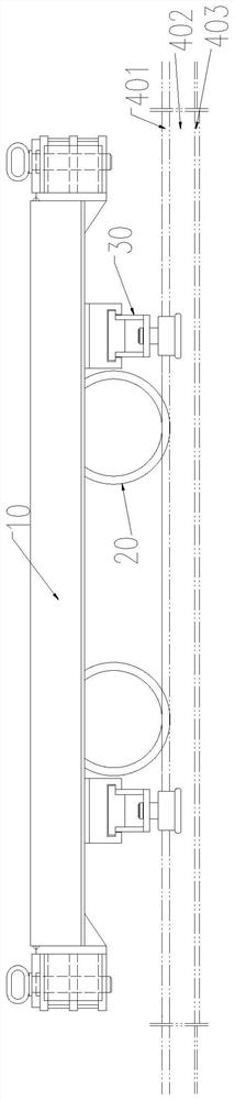
[0044] See figure 1 and figure 2 , The rail car of the present embodiment is a 4-wheel type rail car, including a vehicle frame 10, wheels 20 and a rail device 30. There are 4 rail holders 30, which are respectively located at the front end of each front wheel and the rear end of each rear wheel in the direction of travel of the rail car. Each rail clamp 30 is fixed on the vehicle frame 10 by welding. The rail car runs on the steel rail 40. The rail 40 includes a rail head 401 , a rail web 402 and a rail bottom 403 , and its cross section is I-shaped.
Embodiment 2
[0045] (Embodiment 2, the second of the rail car)
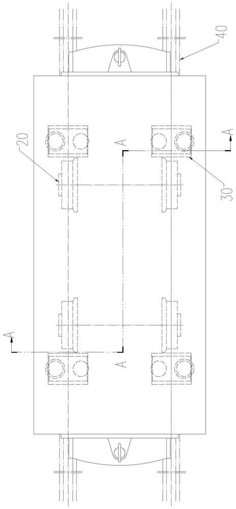
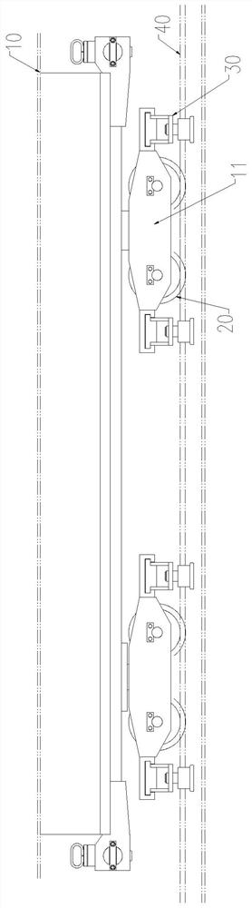
[0046] See image 3 and Figure 4 , The rail car of the present embodiment is an 8-wheel type rail car, including a vehicle frame 10, a bogie 11, wheels 20 and a rail device 30. There are 2 bogies 11, and 8 wheels 20 and rail clamps 30. The vehicle frame 10 is installed on two bogies 11 . Each bogie 11 is provided with 4 wheels 20, and 8 rail clamps 30 are respectively located at the front end of each front wheel and the rear end of each rear wheel on the bogie 11 in the traveling direction of the rail car. Each rail holder 30 is fixed on the bogie frame 11 by welding.
Embodiment 3
[0047] (Embodiment 3, one of the rail clamps)
[0048] The rail holder 30 in the above-mentioned two embodiments is the same type, combined below Figure 5 to Figure 7 Describe it.
[0049] See Figure 5 to Figure 7 , The rail clamp 30 includes a fixed seat 31 and a sliding seat 32 . The fixing seat 31 is connected with the frame 10 or the bogie 11 . Its connection can be through welding or mechanical connection, preferably detachable connection. The bottom of the fixing base 31 is hollow to form a T-shaped groove. The top of the slide seat 32 is convex. Through the hollow at the bottom of the fixing seat 31 and the protrusion at the top of the sliding seat 32, the two are nested and connected in a "T" shape. The T-shaped groove of the fixed seat 31 is used as a guide groove, and the sliding seat 32 can slide left and right relative to the fixed seat 31 .
[0050] The sliding seat 32 is an integral structure, the middle part is hollow and runs through from left to right...
PUM
 Abstract
Description
Claims
Application Information