
Safety television signal receiving device

A TV signal and receiving device technology, which is applied in the field of safe TV signal receiving devices, can solve problems such as difficulty in achieving adjustment effects, time-consuming and labor-consuming, and increased difficulty, so as to achieve convenient and labor-saving adjustment of school teams, improve signal reception quality, reduce The effect of device complexity

Inactive Publication Date: 2017-10-24
顾宁
View PDF0 Cites 0 Cited by
  • Summary
  • Abstract
  • Description
  • Claims
  • Application Information

AI Technical Summary

Problems solved by technology

[0002] At present, digital TV has been used in some cities, but in some remote rural areas, the signal quality is poor. People usually install a TV signal receiver to receive the signal to improve the TV signal quality. However, when the TV signal receiver is installed and checked, The adjustment of azimuth and angle is required to be extremely precise. In the prior art, the adjustment of azimuth and angle is manually adjusted. Due to the instability of manual adjustment, it is more difficult to adjust the school team, which is not only time-consuming and labor-intensive, but also It is difficult to achieve the ideal adjustment effect, and there are major disadvantages, which need to be improved

Method used


Image

  • Safety television signal receiving device
  • Safety television signal receiving device
  • Safety television signal receiving device

Examples


Embodiment Construction

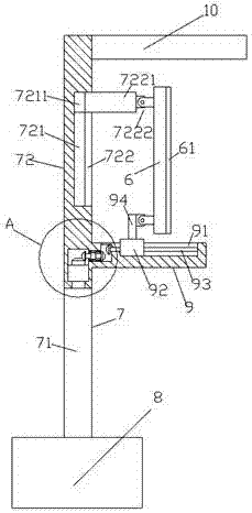
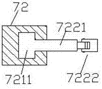
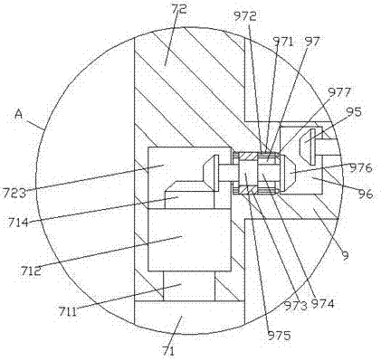
[0020] like Figure 1-Figure 5 As shown, a security television signal receiving device of the present invention includes a bracket rod 7 composed of an upper rod 72 and a lower rod 71 and a bracket 9 fixedly connected with the upper rod 72. The lower rod The bottom of 71 is fixedly connected with the base 8, the inner bottom of the upper rod 72 is provided with a steering groove 723, the upper part of the lower rod 71 is fixedly provided with a steering shaft 711, and the upper part of the steering shaft 711 passes through the upper rod The bottom of the part 72 enters into the steering groove 723, the upper part of the steering shaft 711 is fixedly provided with a fixing block 712, the upper part of the fixing block 712 is provided with a first rack plate 714, and the bracket 9 is fixedly arranged on the On the upper rod 72 outside the right side of the steering groove 723, a second sliding groove 91 is provided in the upper part of the bracket 9, and a second sliding block 9...


PUM


Abstract

The invention discloses a safe television signal receiving device, which comprises a support rod composed of an upper rod and a lower rod and a bracket fixedly connected with the upper rod, the bottom of the lower rod is fixedly connected with a base, and the upper rod The inner bottom is provided with a steering groove, and the upper part of the lower rod is fixed with a steering shaft. The upper part of the steering shaft passes through the bottom of the upper rod and enters into the steering groove. The rack plate, the bracket is fixed on the upper rod outside the right side of the steering slot, the upper part of the bracket is provided with a second sliding slot, and the second sliding slot is provided with a second sliding block and a second spiral Rod, the second sliding block is connected with the thread of the second screw rod, the bracket on the left side of the second sliding groove is provided with a first cavity, the left bottom of the first cavity is connected to the right upper part of the steering groove There is a second cavity between them, and the left side of the second screw rod passes through the wall of the bracket to enter the first cavity and is connected in operation.

Description

technical field [0001] The invention relates to the technical field of signal receiving, in particular to a safety TV signal receiving device. Background technique [0002] At present, digital TV has been used in some cities, but in some remote rural areas, the signal quality is poor. People usually install TV signal receivers to receive signals to improve the TV signal quality. However, when the TV signal receivers are installed and calibrated, The adjustment requirements for the orientation and angle are extremely precise. In the prior art, the adjustment of orientation and angle is manually adjusted. Due to the instability of manual adjustment, it is more difficult to adjust the school team, which is not only time-consuming and labor-intensive, but also It is difficult to achieve the ideal adjustment effect, and there are major drawbacks that need to be improved. SUMMARY OF THE INVENTION [0003] The technical problem to be solved by the present invention is to provide...

Claims


Application Information

Patent Timeline
IPC IPC(8): H04N5/44
CPCH04N5/44
Inventor 顾宁
Owner 顾宁
Learn More