Supercharge Your Innovation With Domain-Expert AI Agents!

Sewing Machine

A sewing machine and motor technology, applied in the field of sewing machines, can solve problems such as adjusting the pressure of the presser foot of the cloth

Active Publication Date: 2017-10-31
JUKI CORP
View PDF11 Cites 6 Cited by
  • Summary
  • Abstract
  • Description
  • Claims
  • Application Information

AI Technical Summary

Problems solved by technology

[0005] However, in the conventional sewing machine mentioned above, since a solenoid is used as a driving source for the lifting movement of the cloth presser foot, it is difficult to arbitrarily adjust the presser foot pressure of the cloth presser foot through control.

Method used


Image

  • Sewing Machine
  • Sewing Machine
  • Sewing Machine

Examples


Embodiment Construction

[0065] [Schematic structure of the embodiment]

[0066] Next, a sewing machine as an embodiment of the present invention will be described in detail.

[0067] The sewing machine 100 according to the embodiment of the present invention is a so-called lockstitch sewing machine, and includes various structures such as a balance mechanism and a thread adjuster that a common locket sewing machine has. Since these are well-known structures, description thereof will be omitted.

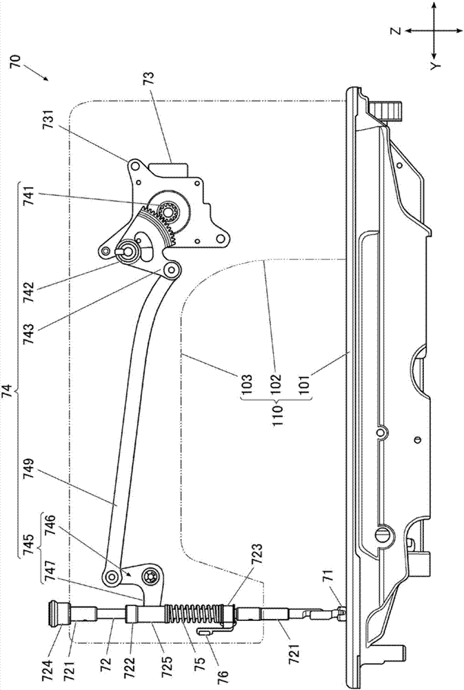
[0068] Above-mentioned sewing machine frame 110 (referring to figure 1 ) has: a sewing machine base part 101, which is located at the lower part of the sewing machine as a whole; a vertical body part 102, which is erected upwardly at one end of the longitudinal direction of the sewing machine base part 101; The upper end portion of the sewing machine base portion 101 is extended in the same direction as the sewing machine base portion 101.

[0069] The front end portion (end portion on the face side) of the ...


PUM


Abstract

The present invention determines the spring type of a replaceable presser foot spring. The sewing machine includes a cloth presser that presses a workpiece to be sewn from above, a presser bar that holds the cloth presser at its lower end, a presser spring that urges the cloth presser via the presser bar, a presser motor, and control device that performs the following control operation: a presser motor is controlled to change and regulate presser pressure of the cloth presser, the presser spring is changed into a plurality of types of presser foot springs having different spring constants, and the control device controls the presser foot motor so that the cloth presser is lowered downwardly upward in a state that the cloth presser is moving away from an upper part relative to a needle plate, the control device has a spring type recognition function, which of the plurality of types of the presser foot springs different in spring constant is the presser foot spring can be identified based on the reaction force received from the presser foot spring during descending of the cloth presser.

Description

technical field [0001] The invention relates to a sewing machine capable of controlling the pressure of the presser foot of the cloth presser. Background technique [0002] Current sewing machines have a presser foot mechanism consisting of a presser bar that holds the material presser foot, and a presser spring that applies downward presser pressure to the material presser foot via the presser bar. a rod that applies a rising motion to the presser bar against the presser spring; and a solenoid that applies a rising motion to the rod via a plurality of link bodies. [0003] In addition, when the material presser foot is lowered, the solenoid is not driven or the thrust is minimized, and the material is pressed by the spring pressure of the presser foot spring, and when the material presser foot is raised, the solenoid is driven to raise it. action (for example, refer to Patent Document 1). [0004] Patent Document 1: Japanese Unexamined Patent Publication No. 2011-092523 ...

Claims


Application Information

Patent Timeline
Patent Type & Authority Applications(China)
IPC IPC(8): D05B29/02
CPCD05B29/02
Inventor 春日俊明中山元射越悠
Owner JUKI CORP
Features
  • R&D
  • Intellectual Property
  • Life Sciences
  • Materials
  • Tech Scout
  • Unparalleled Data Quality
  • Higher Quality Content
  • 60% Fewer Hallucinations
Learn More