An extruder for uniform extrusion of cables

An extruder, uniform technology, applied in the manufacture of cables/conductors, insulation of conductors/cables, circuits, etc., can solve the problems of poor cable quality, uniform mixing of ingredients, breakage, etc., to reduce time waste and extrude uniformly. , the effect of reducing production costs

Active Publication Date: 2019-11-01
冠纳电缆有限公司
View PDF6 Cites 0 Cited by
  • Summary
  • Abstract
  • Description
  • Claims
  • Application Information

AI Technical Summary

Problems solved by technology

[0002] The extruder is an important plastic machine. The production and manufacture of most plastic products can be realized by extrusion molding. The extruder motor is an important part of the extruder and the prime mover of the extruder. It provides For the large thrust required by the extruder screw, a low-speed high-torque permanent magnet direct drive motor is designed for the current general-purpose screw extruder, which has high efficiency, high power density, good energy saving, high reliability, It has many advantages such as high control precision, but because the plastic in the barrel of the extruder is a plastic colloid in a high-temperature molten state when the extruder is working, and the permanent magnet motor is directly connected to the screw of the extruder, most of the existing extruders directly use a single threaded rod. Pressurized extrusion, in this method, the ingredients are not stirred evenly in advance, and the preheating treatment is carried out, resulting in uneven extrusion, air holes will be generated in the middle, and at the same time, fractures may occur during the extrusion process, making The post-production cables are very complicated and the quality of the produced cables is poor

Method used


Image

  • An extruder for uniform extrusion of cables
  • An extruder for uniform extrusion of cables

Examples


Embodiment Construction

[0014] The standard parts used in the present invention can be purchased from the market, and the special-shaped parts can be customized according to the description in the manual and the drawings. The specific connection methods of each part adopt the mature bolts, rivets and welding in the prior art. Conventional methods such as, pasting, etc. will not be described in detail here.

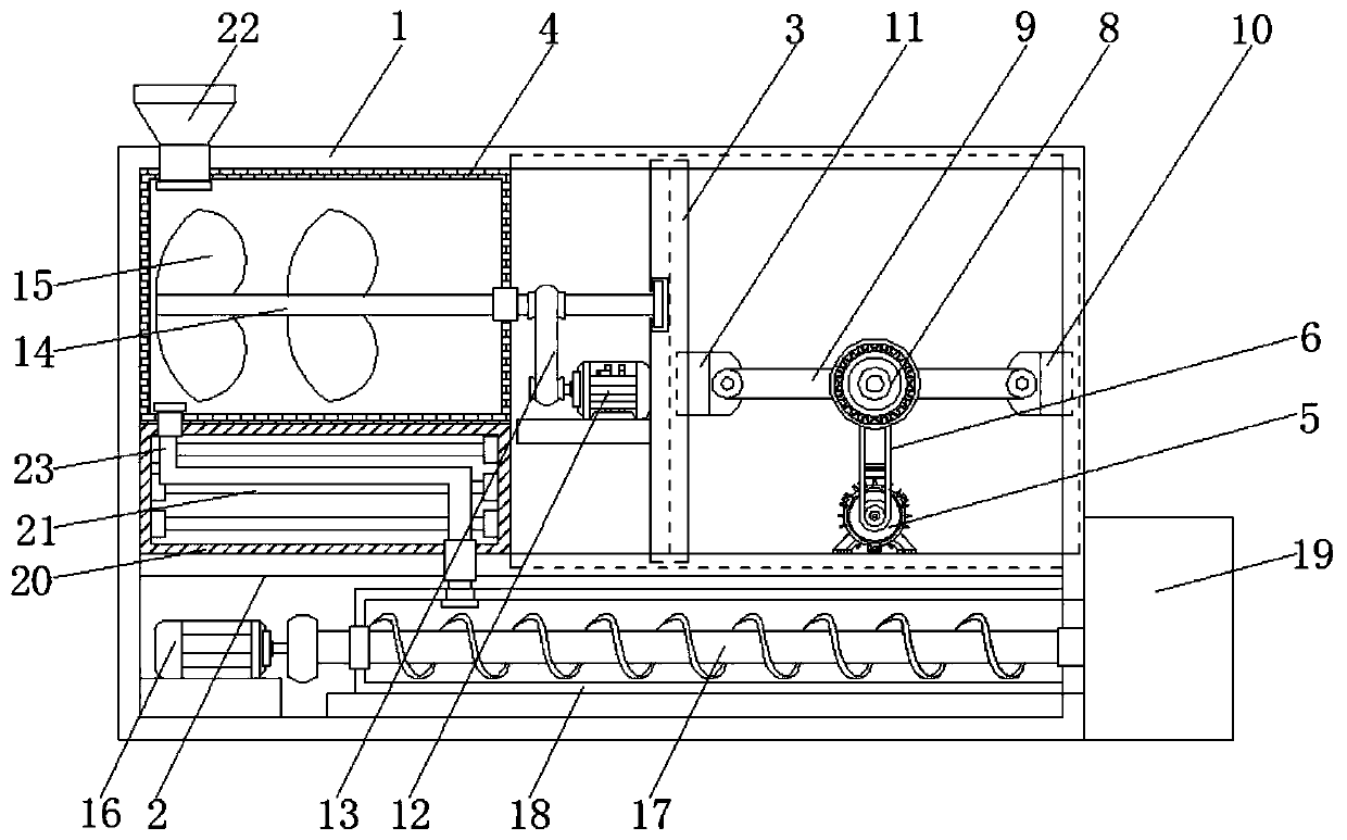
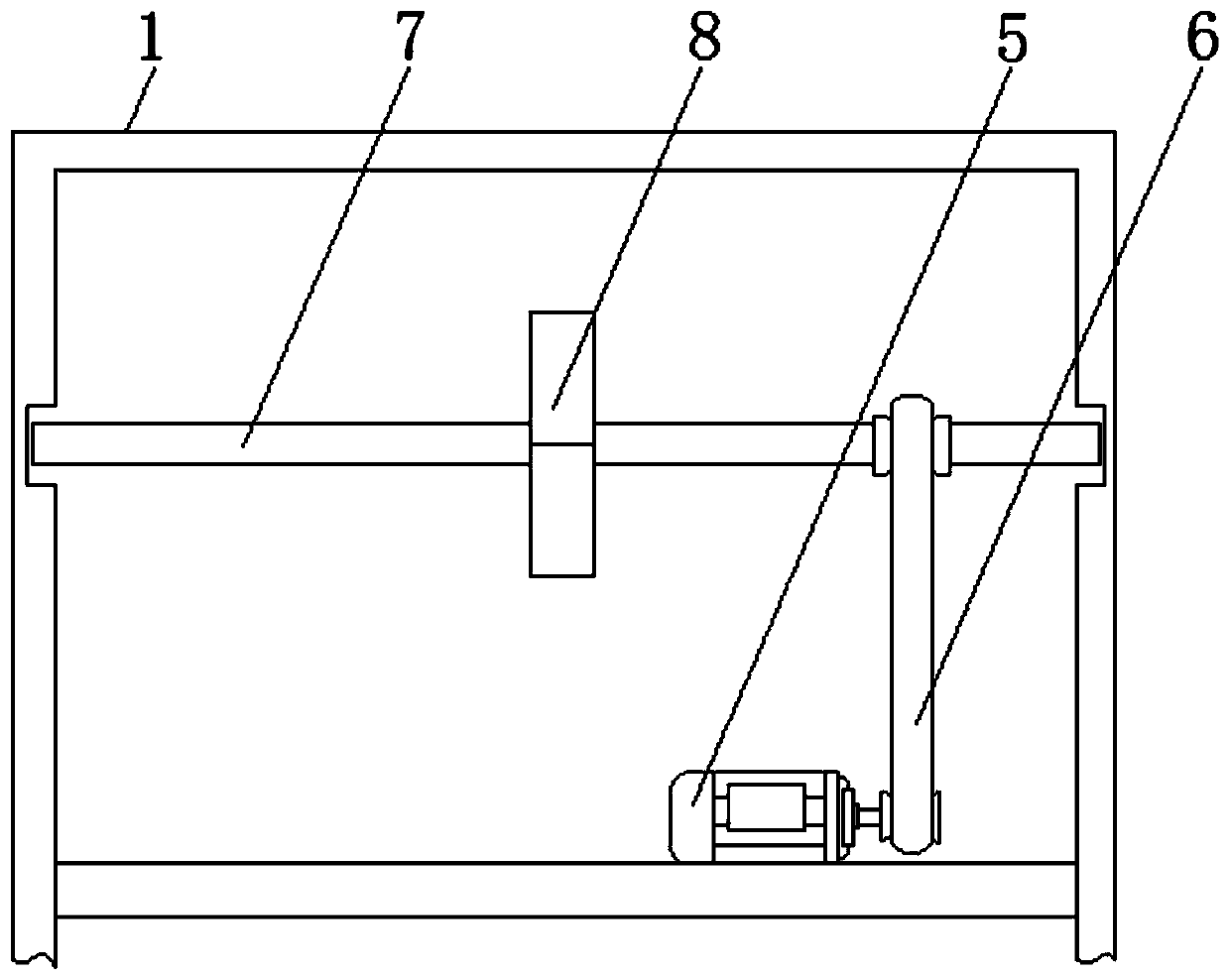
[0015] Reference Figure 1-2 , A specific embodiment of the present invention includes a box body 1, a bottom plate 2 is fixedly connected between the two sides of the inner wall of the box body 1, a support plate 3 is slidably connected between the top of the bottom plate 2 and the top of the inner wall of the box body 1, and the box body 1 A mixing box 4 is fixedly connected between the two sides of the inner wall, a preheating box 20 is fixedly connected between the top of the bottom plate 2 and the bottom of the mixing box 4, and a heating tube 21 is arranged inside the preheating box 20 for pre...


PUM


Abstract

The invention discloses an extruding machine facilitating uniform extrusion of cables. The extruding machine facilitating uniform extrusion of cables comprises a tank. A bottom board is fixedly connected between the two sides of the inner wall of the tank. A supporting board is slidably connected between the top of the bottom board and the top of the inner wall of the tank. A stirring tank is fixedly connected between the two sides of the inner wall of the tank. A first motor is fixedly connected with the right side of the top of the bottom board. An output shaft of the first motor is in transmission connection with a first belt through a belt pulley. A rotary shaft is in transmission connected with the side, away from the first motor, of the first belt. A rotating rod is engaged to the outer side of a gear. A first sliding block is rotationally connected to the right end of the rotating rod. A stirring shaft is in transmission connection with the side, away from a second motor, of a second belt. The left end of the stirring shaft penetrates through the stirring tank and extends into the stirring tank. Stirring vanes are fixedly connected to the surface of the end, extending into the stirring tank, of the stirring shaft. The extruding machine facilitating uniform extrusion of cables can overcome the defects in the prior art and has a better uniform extrusion function.

Description

Technical field [0001] The invention relates to the technical field of extruders, in particular to an extruder that facilitates uniform extrusion of cables. Background technique [0002] Extruder is an important plastic machine. The production and manufacture of most plastic products can be realized by extrusion molding. The motor of the extruder is an important part of the extruder and the prime mover of the extruder. For the large thrust required by the screw of the extruder, a low-speed and large-torque permanent magnet direct drive motor is designed for the current general screw extruder. It has high efficiency, high power density, good energy saving, high reliability, There are many advantages such as high control accuracy, but because the plastic in the barrel is a high-temperature molten plastic colloid when the extruder is working, and the permanent magnet motor is directly connected to the extruder screw, most of the existing extruders use single-threaded rods directly ...

Claims


Application Information

Patent Timeline
Patent Type & Authority Patents(China)
IPC IPC(8): B29C48/154B29C48/285B29C48/78B29C48/25H01B13/14H01B13/24B29L31/34
CPCB29C48/15B29C48/252B29C48/287B29C48/288B29C48/793B29L2031/3462H01B13/14H01B13/24
Inventor 王云飞
Owner 冠纳电缆有限公司
Why Eureka
Try Eureka