Automobile charging pile

A car charging and charging cable technology, applied in electric vehicle charging technology, charging stations, electric vehicles, etc., can solve the problems of people stepping on, car rolling, charging cable life shortening, charging cable insulation damage, etc., to reduce labor costs. The effect of manually retracting the charging cable, preventing accidental electric shock, and improving work efficiency

Inactive Publication Date: 2017-11-03
SHENZHEN CITY HAIDUN HARDWARE TOOLS CO LTD
View PDF0 Cites 8 Cited by
  • Summary
  • Abstract
  • Description
  • Claims
  • Application Information

AI Technical Summary

Problems solved by technology

[0003] The charging pile is an important part of the electric vehicle charging / swapping station. The standard charging pile comes with a charging cable and a charging gun. The charging cable has a certain length. Since the current charging pile does not have the function of automatically winding the charging cable, if Throw the charging cable on the ground at will, so that the charging cable is vulnerable to various unexpected stresses, such as people stepping on it, rolling over by a car, etc., which will cause the outer insulation of the charging cable to be damaged, resulting in a decrease in the life of the charging cable; Safety voltage, once the insulation is damaged, there will be safety hazards such as abnormal insulation, if it is not found in time, it will cause accidents such as electric shock

Method used


Image

  • Automobile charging pile
  • Automobile charging pile
  • Automobile charging pile

Examples


Embodiment Construction

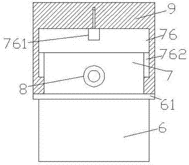
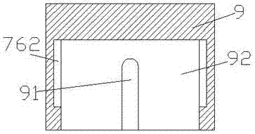
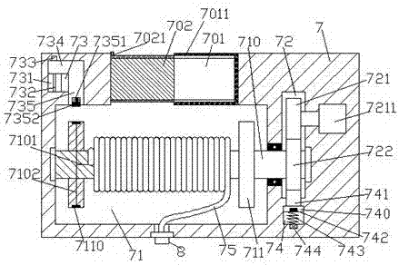
[0026] Such as Figure 1-Figure 8 As shown, a car charging pile of the present invention includes a support column 6, a body 7 fixed on the top of the support column 6, and a lifting protective cover 9 arranged outside the top of the body 7, and the body 7 is provided with The first cavity 71, the body 7 on the right side of the first cavity 71 is provided with a second cavity 72, and the body 7 above the left side of the first cavity 71 is provided with a first slide cavity 73, the body 7 below the second cavity 72 is provided with a second sliding cavity 74, the first cavity 71 is provided with a rotating shaft 710 extending to the left and right sides, and the rotating shaft The extension section on the right side of 710 runs through the inner wall of the body 7 and extends into the second cavity 72 and is connected in a rotational fit. The rotating shaft 710 in the first cavity 71 is symmetrically provided with baffles 711 left and right, The rotating shaft 710 between th...


PUM


Abstract

The invention discloses an automobile charging pile comprising a supporting column, a unit body and a lifting protective cover, wherein the unit body is fixed to the top of the supporting column, and the lifting protective cover is arranged on the outer side of the top of the unit body. A first cavity is formed in the unit body; a second cavity is formed in the part, on the right side of the first cavity, of the unit body; a first sliding cavity is formed in the part, above the left side of the first cavity, of the unit body, and a second sliding cavity is formed in the part, below the second cavity, of the unit body; a rotating shaft extending towards the left side and the right side is arranged in the first cavity; the extending section on the right side of the rotating shaft penetrates through the inner wall of the unit body and extends into the second cavity to be rotationally connected with the second cavity in a matched mode; baffles are arranged in the positions, in the first cavity, of the rotating shaft in a bilaterally-symmetrical mode; a charging wire is arranged in the position, between the baffles, on the rotating shaft in an embracing mode; a first wire is arranged inside the left side of the rotating shaft; the tail end of the left side of the charging wire is embedded into the rotating shaft and electrically connected with the first wire; and a conductive annular piece is arranged outside the baffle on the left side in an embracing mode. The structure is simple, operation is convenient, the charging wire can be automatically wound, meanwhile, safety is improved, and accidental electric-shock accidents are prevented.

Description

technical field [0001] The invention relates to the technical field of new energy vehicles, in particular to a vehicle charging pile. Background technique [0002] Electric vehicles refer to vehicles powered by vehicle-mounted power supplies, driven by motors to drive wheels, and meeting the requirements of road traffic and safety regulations. Compared with gasoline engine vehicles, electric vehicles have less impact on the environment and can replace the use of non-renewable energy gasoline. Therefore, the prospect of electric vehicles is widely optimistic, and it also meets the requirements of new energy strategies. [0003] The charging pile is an important part of the electric vehicle charging / swapping station. The standard charging pile comes with a charging cable and a charging gun. The charging cable has a certain length. Since the current charging pile does not have the function of automatically winding the charging cable, if Throw the charging cable on the ground a...

Claims


Application Information

Patent Timeline
Patent Type & Authority Applications(China)
IPC IPC(8): B60L11/18
CPCB60L53/14B60L53/30B60L53/31Y02T10/70Y02T10/7072Y02T90/12Y02T90/14
Inventor 戚祖盛
Owner SHENZHEN CITY HAIDUN HARDWARE TOOLS CO LTD
Why Eureka
Try Eureka