Antenna module structure and communication terminal

An antenna module and antenna technology, applied in the field of communication, can solve the problems of small antenna wiring area of ​​antenna parts, unfavorable antenna performance, increase the thickness of communication products, etc., and achieve the effect of simplifying product structure and reducing thickness

Pending Publication Date: 2017-11-03
SUNWAY COMM BEIJING
View PDF7 Cites 2 Cited by
  • Summary
  • Abstract
  • Description
  • Claims
  • Application Information

AI Technical Summary

Problems solved by technology

[0002] The earphone jack and the antenna of the current communication products are set as two parts separately. Generally, the antenna part is made and covered on the earphone jack part. This design method will increase the thickness of the communication product, and the antenna part The area of ​​the antenna trace is small, which is not conducive to improving the performance of the antenna

Method used


Image

  • Antenna module structure and communication terminal

Examples


Embodiment 1

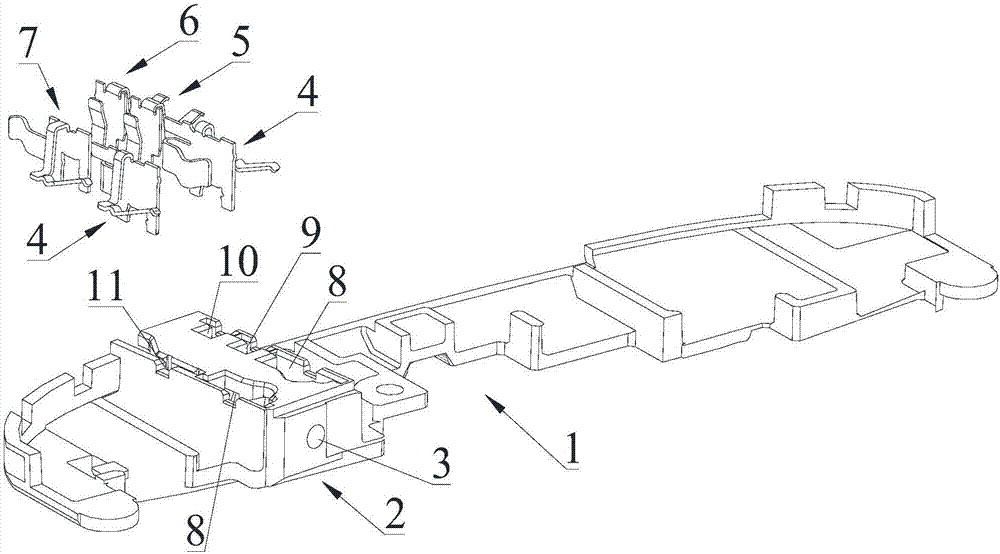
[0032] Please refer to figure 1 , Embodiment 1 of the present invention is:

[0033] A communication terminal includes an antenna module structure.

[0034] Such as figure 1 As shown, the antenna module structure includes an antenna support 1, and the antenna support 1 is provided with an antenna wiring area and a non-antenna wiring area, the antenna wiring area is provided with an antenna wiring, and the non-antenna wiring area An earphone interface structure is arranged on the wiring area, the antenna wiring is located on one side of the antenna bracket 1 , and the earphone interface structure is located on the other side of the antenna bracket 1 . The earphone interface structure includes an earphone jack 3 and an earphone interface bracket 2, the earphone jack 3 is located in the earphone interface bracket 2, and the earphone interface bracket 2 is fixedly arranged on the non-antenna wiring area, preferably, The earphone jack bracket 2 is integrally formed with the ante...


PUM


Abstract

The invention discloses an antenna module structure and a communication terminal. The antenna module structure comprises an antenna support, wherein an antenna wire is arranged on the antenna support; an earphone jack structure is further arranged on the antenna support; the earphone jack structure comprises an earphone jack and an earphone jack support; the earphone jack is positioned inside the earphone jack support; and the earphone jack support is fixedly arranged in the area, not provided with the antenna wire, of the antenna support. According to the antenna module structure, the performance of the antenna can be guaranteed, the earphone jack structure can also be integrated, the thickness of the communication terminal can be reduced, and the development of the communication terminal to lightening and thinning directions is facilitated.

Description

technical field [0001] The invention relates to the technical field of communication, in particular to an antenna module structure and a communication terminal. Background technique [0002] The earphone jack and the antenna of the current communication products are set as two parts separately. Generally, the antenna part is made and covered on the earphone jack part. This design method will increase the thickness of the communication product, and the antenna part The area of ​​the antenna wiring is small, which is not conducive to improving the performance of the antenna. Contents of the invention [0003] The technical problem to be solved by the present invention is to provide an antenna module structure and a communication terminal with an earphone interface function. [0004] In order to solve the problems of the technologies described above, the technical solution adopted in the present invention is: [0005] An antenna module structure, comprising an antenna brack...

Claims


Application Information

Patent Timeline
Patent Type & Authority Applications(China)
IPC IPC(8): H01Q1/12H01Q1/36H01R13/46H01R13/10
CPCH01Q1/12H01Q1/36H01R13/10H01R13/46
Inventor 彭勃
Owner SUNWAY COMM BEIJING
Why Eureka
Try Eureka