Self-tightening clamping connection structure and dish washer
A technology of self-tightening and connecting structure, which is applied in the direction of tableware washing machine/rinsing and washing machine parts, etc., which can solve the problem of loose connection between the clamp strip and the plate body, which cannot be clamped into the hook hole, and is unfavorable for the application and promotion of the clamp structure. And other issues
- Summary
- Abstract
- Description
- Claims
- Application Information
AI Technical Summary
Problems solved by technology
Method used
Image
Examples
Embodiment 1
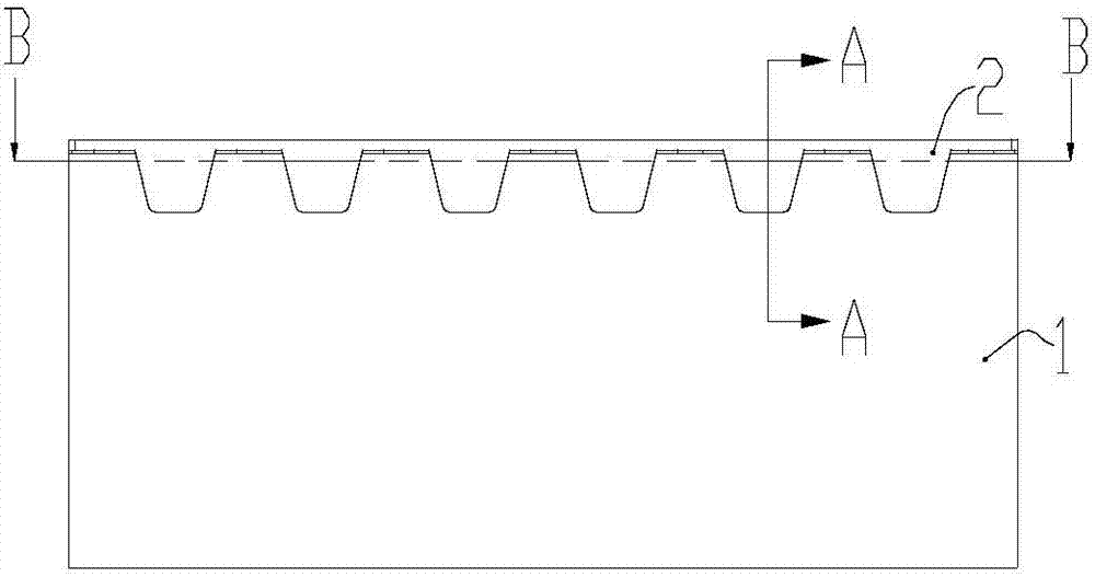
[0033] Such as figure 1 As shown, according to a self-tightening clamping structure in a preferred embodiment of the present invention, the board body 1 and the clamping strip 2 clamped to the edge of the board body 1 . in:
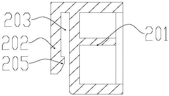
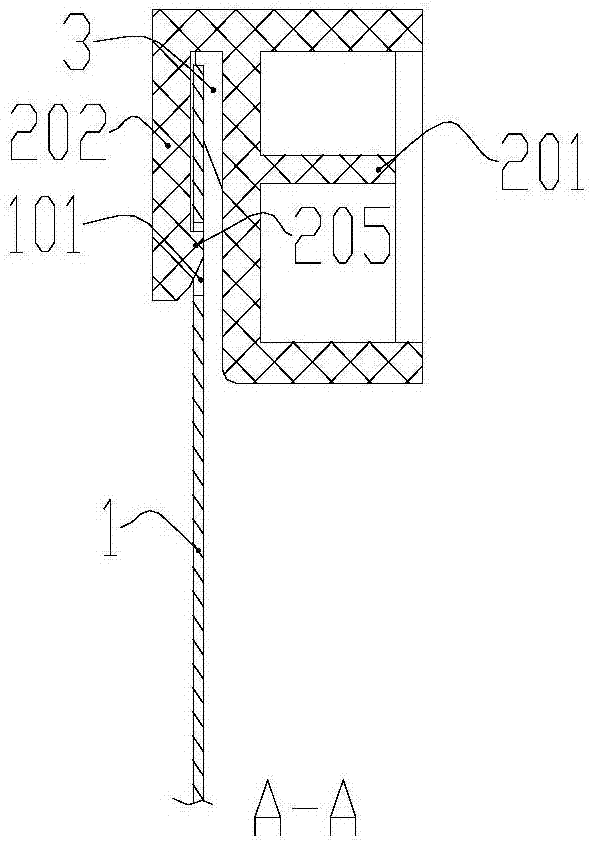
[0034] Such as figure 2 As shown in the cross-sectional view, the clip 2 includes a clip body 201 and a hook portion 202, and the interval between the hook portion 202 and the clip body 201 forms a clip slot 203 into which the plate body 1 snaps, and, in order to facilitate The board body 1 is snapped into the slot 203 , and the width of the slot 203 is greater than the thickness of the board body 1 . A buckle 205 is provided on the side of the hook part 202 facing the bar body 1, combined with image 3 As shown in , a hook hole 101 matching the shape and size of the buckle 205 is formed on the plate body 1 . When the board body 1 and the clip bar 2 are assembled, the buckle 205 is inserted into the hook hole 101 .
[0035] combine image 3 and Fi...
Embodiment 2
[0041] Such as Figure 7 As shown in , according to another preferred embodiment of the present invention, the self-tightening clamping structure differs from Example 1 in that: a clamping protrusion 102 is provided on the plate body 1 corresponding to the buckle 205, and the clamping protrusion 102 is provided on the plate body 1 corresponding to the buckle 205. Under the action of the component 3, the locking protrusion 102 is pressed against the inner surface of the hook portion 202, and the pressing force acts between the two.
Embodiment 3
[0043] Such as Figure 8As shown in , the self-tightening clamping structure according to another preferred embodiment of the present invention differs from that of Embodiment 1 in that: the introduction limiting member is integrally arranged on the plate body 1 . At this time, it should be noted that during the assembly process, the plate body is snapped into the slot 203 along the direction of the arrow in the figure, and after the buckle 205 enters the hook hole 101, the plate body is rotated until the limit surface 302 abuts against the bar body 201 fit.
PUM
 Abstract
Description
Claims
Application Information
 - R&D
- Intellectual Property
- Life Sciences
- Materials
- Tech Scout
- Unparalleled Data Quality
- Higher Quality Content
- 60% Fewer Hallucinations
Browse by: Latest US Patents, China's latest patents, Technical Efficacy Thesaurus, Application Domain, Technology Topic, Popular Technical Reports.
© 2025 PatSnap. All rights reserved.Legal|Privacy policy|Modern Slavery Act Transparency Statement|Sitemap|About US| Contact US: help@patsnap.com


