Heat-released welding method of ground lead in Amazon rainforest

An exothermic welding and tropical rainforest technology, applied in aluminothermic welding equipment, welding equipment, metal processing equipment, etc., can solve problems such as increasing operation and maintenance costs, shortening the service life of the grounding system, and accelerating corrosion of flexible grounding wires. Reduce production costs, reduce post-maintenance and repair work, and stabilize the grounding conductor

Active Publication Date: 2017-11-07
POWERCHINA SEPCO1 ELECTRIC POWER CONSTR CO LTD
View PDF7 Cites 1 Cited by
  • Summary
  • Abstract
  • Description
  • Claims
  • Application Information

AI Technical Summary

Problems solved by technology

This connection method not only causes the flexible grounding wire to be unreliably and firmly connected, but also the galvanized layer of the joint part is subject to repeated abrasions during the construction process, and the flexible grounding wire accelerates corrosion in the humid environment of the Amazon rainforest because the joint part is in direct contact with the soil , which greatly shortens the service life of the grounding system and seriously affects the safe and stable operation of the grounding system
[0003] Therefore, this flexible grounding wire bolt connection technology cannot reliably and firmly connect the segmented grounding wires, and the conductivity stability is poor; The accelerated corrosion of the grounding system in the humid environment of the Amazon rainforest is not conducive to the safe and stable operation of the grounding system
The service life of the grounding system is shortened, which increases the work intensity of the later operation and maintenance personnel on the maintenance and transformation of the grounding system, and increases the cost of operation and maintenance

Method used


Image

  • Heat-released welding method of ground lead in Amazon rainforest

Examples


Embodiment 1

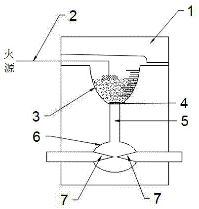
[0040] S1. Divide 30 joints 7 to be welded into three groups, and each group is 10 joints to be welded 7. Use arc cutting pliers to cut the joints 7 to be welded at the joints of the three groups of grounding wires into cone angles of 50° for the first group and 50° for the second group. Two groups of 60 ° and the third group of 70 ° conical, the length of the conical portion of each joint 7 to be welded is 1 / 2 of the length of the mold welding chamber 6;

[0041] S2, tie up the joint 7 to be welded of the grounding wire with an iron wire, and dry and preheat the mold and the joint 7 to be welded with a torch;

[0042] S3. Wipe the joint 7 to be welded with cotton gauze until the oxide layer is removed and the metal luster is completely exposed, and the mold is cleaned at the same time;

[0043] S4. Put the joint to be welded 7 into the mold welding chamber 6 so that the welded joint to be formed is directly facing the outlet of the mold diversion groove 5 center, and the pair...

Embodiment 2

[0050] S1, cutting 30 joints 7 to be welded into a conical shape with a cone angle of 60°, and the length of the cone of each joint 7 to be welded is 1 / 2 of the length of the mold welding chamber 6;

[0051] S2, tie up the joint 7 to be welded of the grounding wire with an iron wire, and dry and preheat the mold and the joint 7 to be welded with a torch;

[0052] S3. Wipe the joint 7 to be welded with cotton gauze until the oxide layer is removed and the metal luster is completely exposed, and the mold is cleaned at the same time;

[0053] S4. Put the joint to be welded 7 into the mold welding chamber 6 so that the welded joint to be formed is directly facing the outlet of the mold diversion groove 5 center, and the pairing gap between the joints to be welded 7 is 1-2 mm;

[0054] S5. Heat the mold and the joint 7 to be welded with a flame gun, and measure the temperature of the two in real time with an infrared temperature measuring gun to ensure that the temperature of both is...

Embodiment 3

[0060] S1, cutting the 30 to-be-welded head into a conical shape with a cone angle of 60°, and the length of the conical portion of each to-be-welded head 7 is 1 / 2 of the length of the mold welding chamber 6;

[0061] S2, tie up the joint 7 to be welded of the grounding wire with an iron wire, and dry and preheat the mold and the joint 7 to be welded with a torch;

[0062] S3. Wipe the joint 7 to be welded with cotton gauze until the oxide layer is removed and the metal luster is completely exposed, and the mold is cleaned at the same time;

[0063] S4. Put the joint to be welded 7 into the mold welding chamber 6 so that the welded joint to be formed is directly facing the outlet of the mold diversion groove 5 center, and the pairing gap between the joints to be welded 7 is 1-2mm;

[0064] S5. Heat the mold and the joint 7 to be welded with a torch, and measure the temperature of the two in real time with an infrared temperature measuring gun to ensure that the temperature of ...


PUM


Abstract

The invention relates to a heat-released welding method of a ground lead in the Amazon rainforest. The heat-released welding method comprises the following steps that to-be-welded heads at the butt joint positions of the ground lead are peeled into a cone with the conical angle being alpha through an arc peeling pincer; the to-be-welded heads of the ground lead are bundled up through an iron wire to be dried; cotton gauze is used for wiping the to-be-welded heads until an oxide layer is removed and metallic luster is completely exposed out; the to-be-welded heads are placed into a die welding chamber to enable a to-be-formed welding head to right face an outlet in the center of a die flow guide groove; a die and the to-be-welded heads are heated; the whole die is heated after the die is closed; a supporting sheet of the die is placed at the bottom of a heat melting chamber; an appropriate amount of welding powder is poured into the heat melting chamber with scale marks, a small amount of pyrophoric powder is scattered, one end of an igniting cable is inserted into the pyrophoric powder, the other end of the igniting cable is led out of the die, and the part, out of the die, of the igniting cable is ignited after a die cover is buckled; and cooling is carried out for 30 s to 50 s after welding is completed, the die is opened, the welding head is taken out to be cleaned and inspected, and antiseptic paint is sprayed to the welding head after the welding head is qualified.

Description

technical field [0001] The invention belongs to the welding technology of grounding wires, and in particular relates to a welding method for grounding wires in the Amazon rainforest. Background technique [0002] In the Amazon rainforest grounding construction, the grounding system mainly uses flexible grounding wires, that is, ordinary galvanized steel strands. The flexible ground wire is laid in sections, with many joints, and the joints are bolted with common connecting hardware. This connection method not only causes the flexible grounding wire to be unreliably and firmly connected, but also the galvanized layer of the joint part is subject to repeated abrasions during the construction process, and the flexible grounding wire accelerates corrosion in the humid environment of the Amazon rainforest because the joint part is in direct contact with the soil , which greatly shortens the service life of the grounding system and seriously affects the safe and stable operation ...

Claims


Application Information

Patent Timeline
Patent Type & Authority Applications(China)
IPC IPC(8): B23K23/00
Inventor 宋维洋庞继勇邵国栋
Owner POWERCHINA SEPCO1 ELECTRIC POWER CONSTR CO LTD
Why Eureka
Try Eureka