Automatic textile winding device

A winding device and automatic technology, which is applied in the field of textile processing, can solve problems such as single structure, bobbin falling off, increasing economic cost, etc., and achieve the effect of improving installation stability, facilitating installation and disassembly, and improving the overall process

Active Publication Date: 2017-11-07
嘉兴市华益股份有限公司
View PDF15 Cites 0 Cited by
  • Summary
  • Abstract
  • Description
  • Claims
  • Application Information

AI Technical Summary

Problems solved by technology

The current winding equipment generally has a single structure, poor functionality, and is inconvenient for users to use, causing great difficulties to users, and it will cause troublesome replacement during winding, which will affect the overall process of winding. When winding, the bobbin is easy to fall off from the bobbin shaft. In the prior art, manual adjustment is generally used, which increases the labor expenditure and improves the economic cost.

Method used


Image

  • Automatic textile winding device
  • Automatic textile winding device
  • Automatic textile winding device

Examples


Embodiment Construction

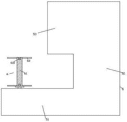
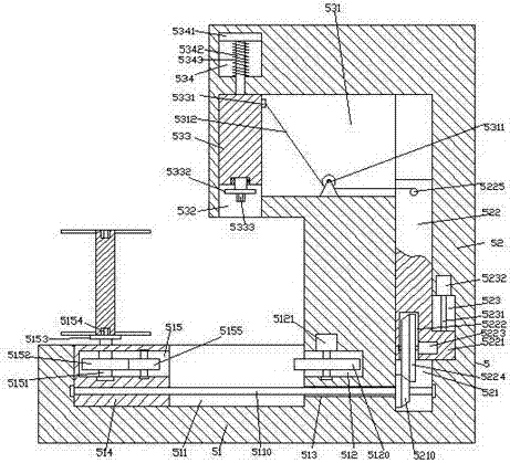
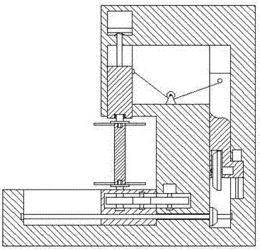
[0024] Such as Figure 1-Figure 5 As shown, an automatic textile winding device of the present invention includes a winding body 5 composed of a first body 51 and a second body 52 fixed on the right side of the first body 51. The first body 51 A first sliding groove 511 is arranged in the top end surface of the right side, and a first sinking groove 512 is arranged in the left end surface of the second body 52 in the first sliding groove 511, and the first sinking groove 512 is rotationally fitted and connected. There is a first toothed wheel 5120, the top of the first toothed wheel 5120 is connected with the first motor 5121, and the second body 52 on the right side of the first sinker 512 is provided with a second vertically extending Sliding groove 521, a third sliding groove 523 is provided in the inner wall on the right side of the second sliding groove 521, and a first threaded rod 5231 extending longitudinally is arranged in the third sliding groove 523, and the first t...


PUM


Abstract

The invention discloses an automatic textile winding device comprising a winding device body which is composed of a first device main body and a second device main body fixed to the right side of the first main body. A first sliding groove is formed in the end face of the top of the right side of the first device main body, and a first sinking groove is formed in the position, in the first sliding groove, of the end face of the left side of the second device main body and connected with a first tooth-shaped wheel in a rotatably-matched mode. The top of the first tooth-shaped wheel is in matched connection with a first motor, and a second sliding groove extending in the longitudinal direction is formed in the position, on the right side of the first sinking groove, of the interior of the second device main body. A third sliding groove is formed in the inner wall of the right side of the second sliding groove and internally provided with a first threaded rod extending in the longitudinal direction, the top of the first threaded rod is in matched connection with a second motor, and a penetration hole extending towards the left side and the right side is formed in the position, below the first sinking groove, of the interior of the second device main body. According to the automatic textile winding device, the structure is simple, operation is convenient, and the effect that a winding cylinder is automatically mounted and locked to be prevented from falling off can be achieved, so that the mounting stability is improved; and automatic extending-in and extending-out of a sliding structure can be achieved, so that quick dismounting and mounting are facilitated, and the replacing speed of the winding cylinder is increased.

Description

technical field [0001] The invention relates to the technical field of textile processing, in particular to an automatic textile winding device. Background technique [0002] Textile is a handicraft industry that serves human clothing. Spinning, weaving, and making clothes are one of the most basic living conditions for people. With the development of the economy, people's living standards continue to improve, and the demand for clothes is increasing. , The demand for production equipment is gradually increasing, and the winding machine is one of them. The current winding equipment generally has a single structure, poor functionality, and is inconvenient for users to use, causing great difficulties to users, and it will cause troublesome replacement during winding, which will affect the overall process of winding. When winding the wire, the bobbin is easy to fall off from the bobbin shaft. In the prior art, manual adjustment is generally used, which increases the expenditur...

Claims


Application Information

Patent Timeline
IPC IPC(8): B65H54/44B65H54/54B65H67/04B65H57/14
CPCB65H54/44B65H54/543B65H57/14B65H67/0405B65H2701/31
Inventor 张莉笛
Owner 嘉兴市华益股份有限公司
Why Eureka
Try Eureka