
Binding structure of display panel and display panel

A display panel and binding technology, applied in instruments, nonlinear optics, optics, etc., can solve the problems of large size of FPCPCB and small screen ratio of display panel, so as to increase screen ratio, reduce binding space, reduce Small volume effect

Inactive Publication Date: 2017-11-07
SHANGHAI AVIC OPTOELECTRONICS
View PDF5 Cites 34 Cited by
  • Summary
  • Abstract
  • Description
  • Claims
  • Application Information

AI Technical Summary

Problems solved by technology

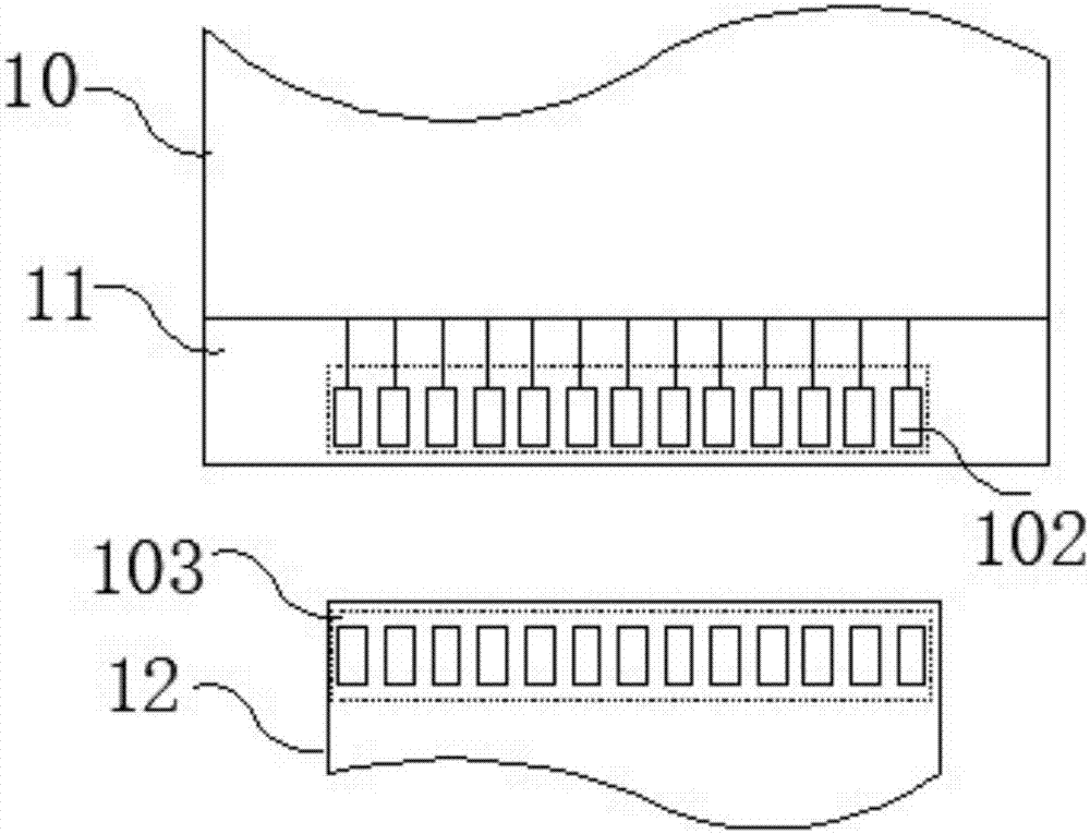
[0007] In view of this, the present invention provides a binding structure of the display panel and the display panel, which solves the technical problems of the small screen-to-body ratio of the display panel and the large volume of the FPC and PCB in the prior art

Method used


Image

  • Binding structure of display panel and display panel
  • Binding structure of display panel and display panel
  • Binding structure of display panel and display panel

Examples


Embodiment Construction

[0026] Various exemplary embodiments of the present invention will now be described in detail with reference to the accompanying drawings. It should be noted that the relative arrangements of components and steps, numerical expressions and numerical values ​​set forth in these embodiments do not limit the scope of the present invention unless specifically stated otherwise.

[0027] The following description of at least one exemplary embodiment is merely illustrative in nature and in no way taken as limiting the invention, its application or uses.

[0028] Techniques, methods and devices known to those of ordinary skill in the relevant art may not be discussed in detail, but where appropriate, such techniques, methods and devices should be considered part of the description.

[0029] In all examples shown and discussed herein, any specific values ​​should be construed as exemplary only, and not as limitations. Therefore, other instances of the exemplary embodiment may have dif...


PUM


Abstract

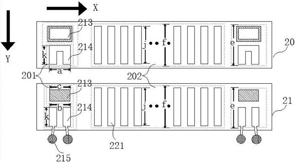
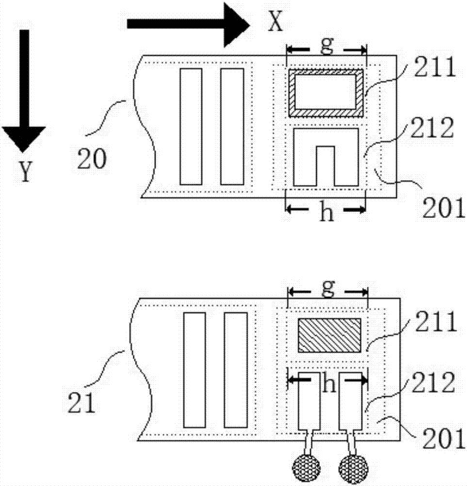
The invention discloses a binding structure of a display panel and the display panel. The binding structure comprises a first binding portion and a second binding portion. The first binding portion and the second binding portion each comprise a base material layer; each base material layer comprises a counterpoint testing region and a conventional finger distribution region, and each counterpoint testing region comprises a counterpoint region and a testing region; the first binding portion and the second binding portion further comprise counterpoint marks arranged inside the counterpoint regions and at least two testing fingers arranged inside the testing regions, a plurality of conventional fingers are arranged inside each conventional finger distribution region, the testing fingers of the first binding portion are in short-circuit connection, and the testing fingers of the second binding portion are arranged in an insulated mode and connected with testing pins. The first binding portion and the second binding portion are correspondingly connected in a pressed mode to form a binding structure. According to the binding structure, on one hand, the fingers at the binding portions at the two ends can be accurately and correspondingly connected in the pressed mode; on the other hand, the testing fingers occupy the small binding space, the display panel screen occupation ratio is increased, and the size of an FPC and the size of a PCB are decreased.

Description

technical field [0001] The present invention relates to the field of display technology, and more specifically, to a binding structure of a display panel and a display panel. Background technique [0002] Display technology refers to the technology that uses electronic technology to provide flexible visual information. With the rapid development of the display field, various electronic devices with display screens are becoming more and more common in daily life. Commonly used display screen application scenarios include: mobile phone screens, Computer monitors, electronic billboards, etc. In order to obtain a better display effect, the requirements for the performance and quality of the display screen are getting higher and higher. [0003] As we all know, the quality of a display screen first depends on its display panel, because the quality of the display panel directly affects the viewing effect of the screen, and the display panel can largely determine the brightness, c...

Claims


Application Information

Patent Timeline
Patent Type & Authority Applications(China)
IPC IPC(8): G02F1/13
Inventor 汤仁波朱志峰王徐鹏樊树全李文静吴茂棒
Owner SHANGHAI AVIC OPTOELECTRONICS
Learn More