
Transient energy function method in consideration of VSG inverter current limitation

A transient energy function and current limiting technology, which is applied in electrical digital data processing, instruments, calculations, etc., can solve problems such as slow calculation speed, no fundamental guidance for safe and stable operation of the power grid, and power angle instability.

Active Publication Date: 2017-11-07
NANJING UNIV OF SCI & TECH
View PDF3 Cites 13 Cited by
  • Summary
  • Abstract
  • Description
  • Claims
  • Application Information

AI Technical Summary

Problems solved by technology

The numerical simulation method obtains the system stability by observing the change of the inverter swing curve under the VSG control strategy after the fault, but it cannot quantitatively evaluate the transient stability of the system. Some numerical simulation methods do not take into account the influence of inverter current saturation characteristics when studying the transient stability of inverter systems with VSG strategies; the transient energy function method overcomes the slow calculation speed and inability to quantify the numerical simulation method Analyzing the limitations of stability, in the study of system stability taking into account the inverter current saturation characteristics, the existing transient energy function method can be concluded that due to the inverter current saturation, the inverse Transformer fades into a current source, which makes the instability process more complicated, and makes a mechanism analysis of power angle instability
However, it is only a qualitative analysis of VSG transient power angle instability, and there is no fundamental guidance for the safe and stable operation of the actual power grid.

Method used


Image

  • Transient energy function method in consideration of VSG inverter current limitation
  • Transient energy function method in consideration of VSG inverter current limitation
  • Transient energy function method in consideration of VSG inverter current limitation

Examples


Embodiment Construction

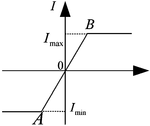
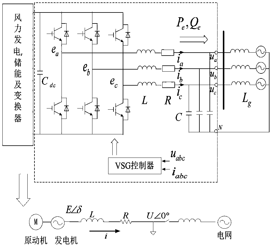
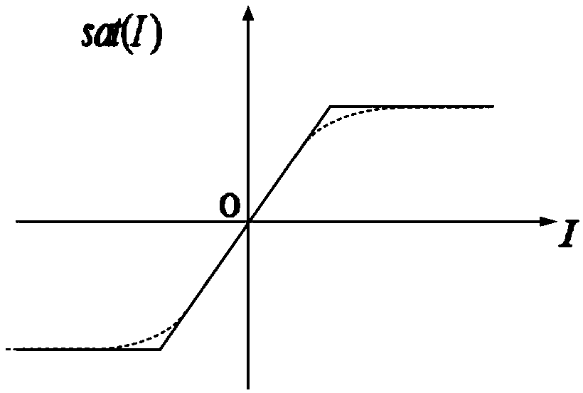
[0022] The invention proposes a transient energy function method of a wind power system under the VSG strategy and considering inverter current limiting. When the inverter current is limited (the actual inverter has a current limit, because the overcurrent will damage the inverter), the traditional transient energy function method cannot judge the transient stability of the VSG (virtual synchronous generator) system In this patent, by improving the model of the inverter current limiting link, the transient energy function taking into account the improved current limiting link is constructed, and the transient stability of the VSG system can be correctly judged. This method considers the limitations of the transient energy function analysis of the current inverter saturation link. On this basis, the current saturation link model is approximately equivalent to an arctangent function, and the inverse The relationship between the virtual power angle and the traditional power syste...


PUM


Abstract

The invention provides a transient energy function method in consideration of VSG inverter current limitation. The method comprises the steps that a current limitation model of an inverter is built; the power-angle characteristic under inverter current saturation is obtained; a system power-angle model in consideration of inverter saturation under a VSG strategy is built; an improved inverter current saturation element model is built, and a relation of an improved power angle and an unsaturated power angle is obtained; main parameters of electric parts are input; a Runge-Kutta method is used for solving a rotor motion equation to obtain delta(t) and dotted delta(t) of a VSG rotor, so that a fault trajectory is obtained, wherein delta(t) represents a relation of the system power angle and time, and dotted delta(t)=w(t) represents a relation of the system angular velocity and time; transient energy Vcl and critical energy Vcr of the system at the fault clearing time are obtained; the obtained transient energy Vcl and critical energy Vcr of the system at the fault clearing time are compared, if Vcl is smaller than or equal to Vcr, the system is stable, otherwise, the system is not stable; critical fault-clearing time is solved.

Description

technical field [0001] The invention relates to a power system transient stability analysis and a nonlinear power electronic device saturation characteristic research technology, in particular to a transient energy function method considering the current limit of a VSG inverter. Background technique [0002] With the continuous expansion of wind power scale, the number of power electronic converters such as grid-connected inverters connected to the grid has also increased rapidly. Because power electronic devices adopt digital circuit control mode, the transient response time is short, when there is a power disturbance or power imbalance in the grid, it is impossible to use the kinetic energy stored in the rotor to suppress power or frequency like a traditional synchronous generator fluctuations. Based on this, in order to solve the stability problem caused by the inertialess characteristics of the inverter in the wind power system, foreign researchers first proposed the vi...

Claims


Application Information

Patent Timeline
IPC IPC(8): G06F17/50
CPCG06F30/20
Inventor 杨阳卜京张梦月王俊涂杉杉周前汪成根张宁宇胡昊明
Owner NANJING UNIV OF SCI & TECH
Learn More