A flow-through contact limiting device in a dynamic connection structure

A technology of limit device and dynamic connection, which is applied in the directions of contacts, electrical components, electric switches, etc., can solve the problems of not meeting the requirements, etc., and achieve the effect of fewer parts, simple and reliable limit structure, and simple structure.

Active Publication Date: 2019-02-12
CHINA XD ELECTRIC CO LTD
View PDF4 Cites 0 Cited by
  • Summary
  • Abstract
  • Description
  • Claims
  • Application Information

AI Technical Summary

Problems solved by technology

There is currently no structure that meets the requirements

Method used


Image

  • A flow-through contact limiting device in a dynamic connection structure
  • A flow-through contact limiting device in a dynamic connection structure
  • A flow-through contact limiting device in a dynamic connection structure

Examples


Embodiment Construction

[0020] The present invention will be further described below in conjunction with drawings and embodiments.

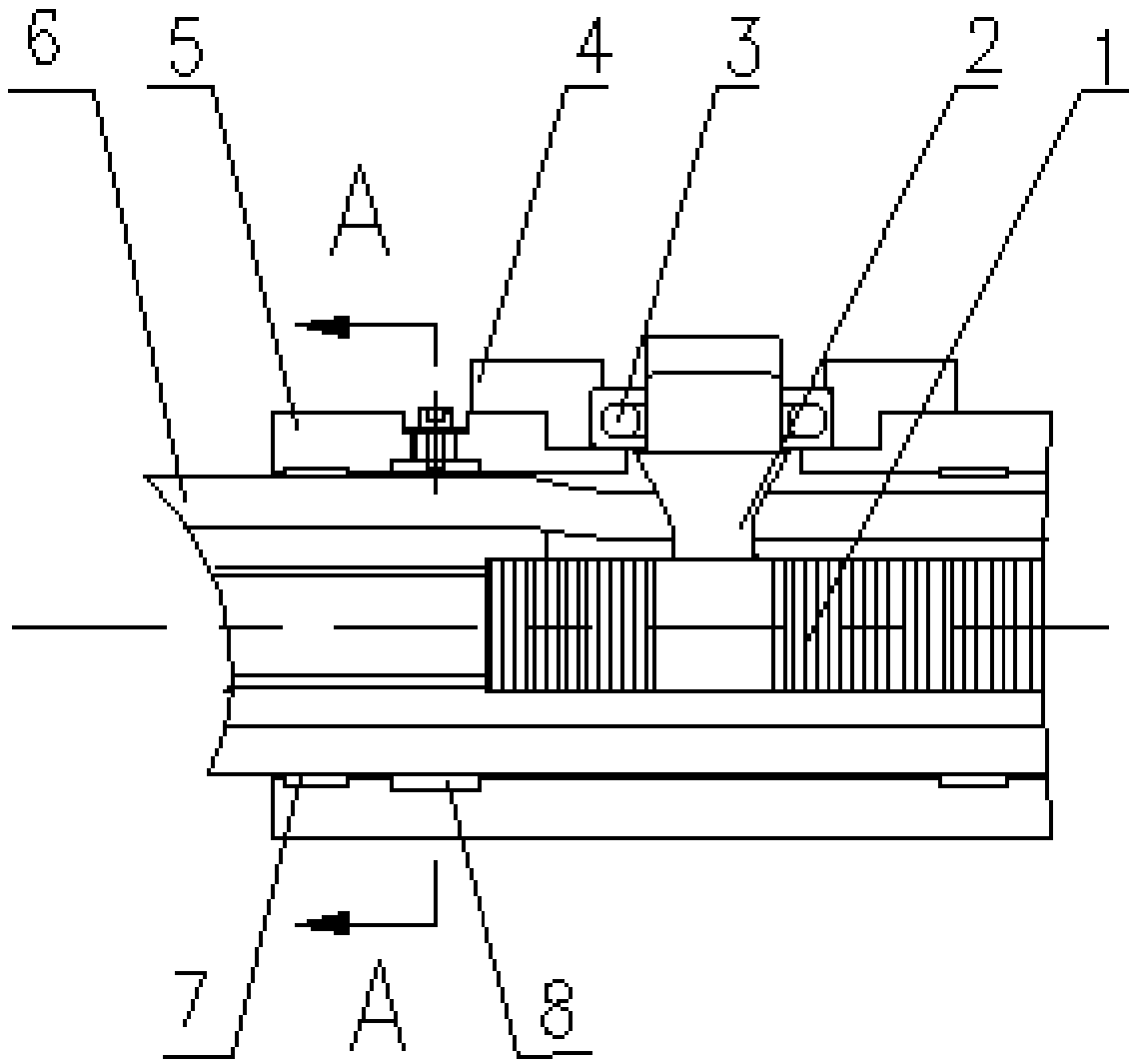
[0021] The purpose of the present invention is to provide a flow contact limiting device in a new type of dynamic connection flow structure for gas insulated metal-enclosed switchgear, which is used to fix the flow contact and ensure that when the conductor moves, the assembly position will not Changed, fixed in the original assembled position, prevents the current contact from being caught in the moving rack.

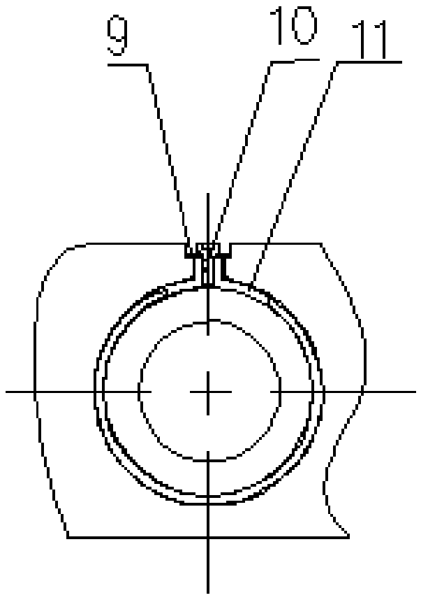
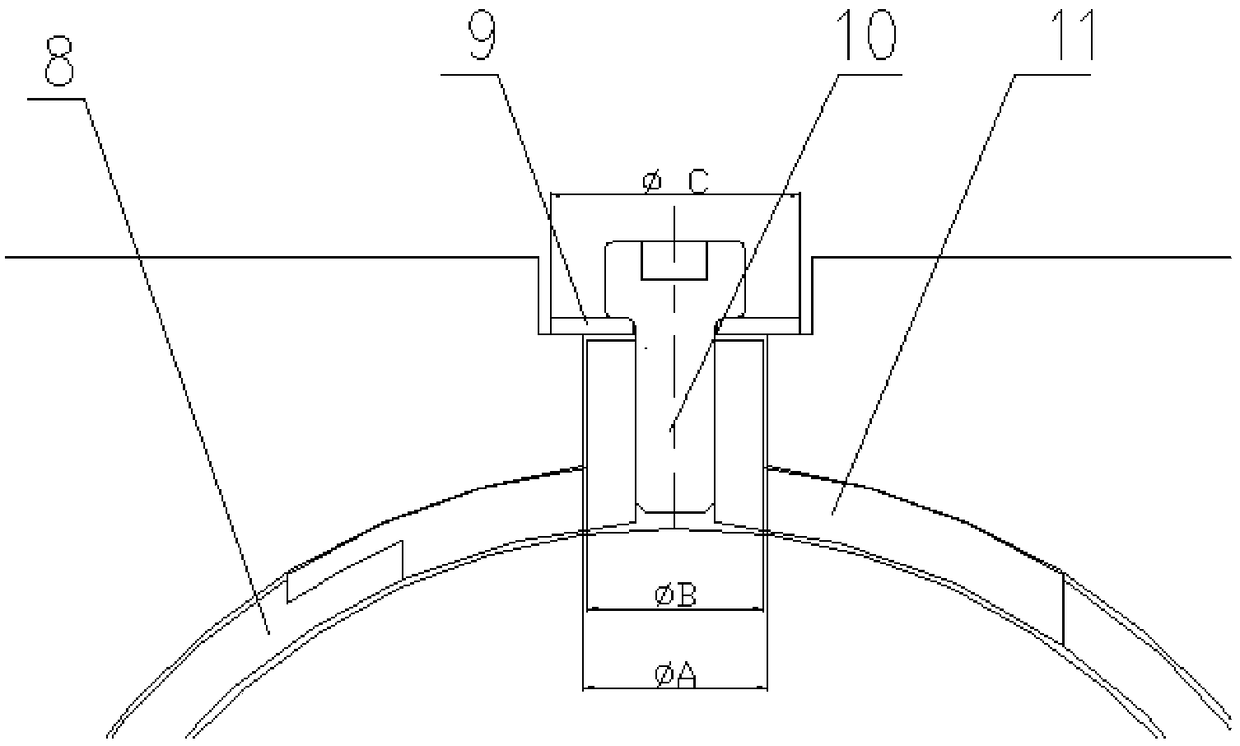
[0022] Please refer to the attached figure 1 , the present invention includes a rack 1, a transmission gear shaft 2, a ball bearing 3, a support ring 4, a contact seat 5, a flow conductor 6, a limit guide sleeve 7, a flow contact 8, a large gasket 9, and a bolt 10 , Contact limit sleeve 11.

[0023] A transmission groove for gear rotation is designed on the current conductor 6, and the rack 1 is fixed in the transmission groove of the current conductor 6, and ...


PUM


Abstract

The invention discloses a flow-through contact stop device in a mobile connection structure. The flow-through contact stop device comprises a tooth bar, a transmission gearshaft, a ball bearing, a support ring, a contact seat, a flow-through conductor, a stop guiding sleeve and a flow-through contact, wherein the flow-through contact between the flow-through conductor and the contact seat for supporting the contact avoid the moving track of the gearshaft, the stop device of the flow-through contact is assembled in a groove for installing the flow-through contact in the contact seat for supporting the flow-through conductor and the transmission gearshaft and used for fixing an original assembly position of the flow-through conductor. In long-time operation of equipment, the flow-through contact moves for multiple times, and display of the position of the flow-through contact assembled between the flow-through conductor and the contact seat for supporting the flow-through conductor and the transmission gearshaft can be prevented. The flow-through contact stop device in the mobile connection structure ensures reliable contact between the flow-through contact and the flow-through conductor and product flow-through reliability, and is essential for long-time reliable operation of equipment.

Description

【Technical field】 [0001] The invention relates to a gas-insulated metal-enclosed switchgear (GIS), in particular to a current-flow contact limiting device in a dynamic connection structure. 【Background technique】 [0002] Gas-insulated metal-enclosed switchgear (GIS) usually has a dynamic connection and flow structure inside, which is mostly used at the contact on the moving side of the component as a flow conductor for flow. In order to achieve internal movement, it is necessary to process the movement on the cylindrical surface of the conductor The card slot is used to cooperate with the transmission gear shaft. The current contact between the current conductor and the contact seat used to support the contact needs to avoid the movement track of the gear shaft. The contact seat and the communication contact are set in the dynamic connection structure. The current contact limit device between the current conductors. [0003] In order to facilitate the double realization of...

Claims


Application Information

Patent Timeline
Patent Type & Authority Patents(China)
IPC IPC(8): H01H1/50
CPCH01H1/50
Inventor 赵晓燕火恒章伊朋
Owner CHINA XD ELECTRIC CO LTD
Why Eureka
Try Eureka