Safety plug device for power supply

A plug-in device and safety technology, applied in the direction of preventing contact with live contacts, components of connecting devices, coupling devices, etc., can solve problems such as child casualties, power failure, loosening, etc., to protect the safety and security of electricity use The effect of stable power supply and high safety

Inactive Publication Date: 2017-11-07
佛山腾谱工业设计有限公司
View PDF3 Cites 8 Cited by
  • Summary
  • Abstract
  • Description
  • Claims
  • Application Information

AI Technical Summary

Problems solved by technology

[0002] Generally, electrical equipment needs to be powered on before it can work, and the electrical equipment is powered by the cooperation of the plug body and the socket body. The traditional plug and socket use the friction between the two to achieve The state is locked when it is inserted, but this locking method is extremely unstable. When the plug body is accidentally touched or lifted, it is easy to separate or loosen the plug body and the socket body. The equipment is prone to failure, and in the traditional socket, the conductive column of the plug can be inserted into the socket to supply power to the electrical equipment, but this structure is not safe enough, for example, in household sockets, some young children who lack safety awareness For children, things like iron rods and keys will be inserted into the jack, which will cause casualties to children, and such reports often appear. Therefore, there are great potential safety hazards in traditional power supply sockets

Method used


Image

  • Safety plug device for power supply
  • Safety plug device for power supply
  • Safety plug device for power supply

Examples


Embodiment Construction

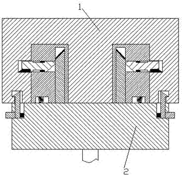
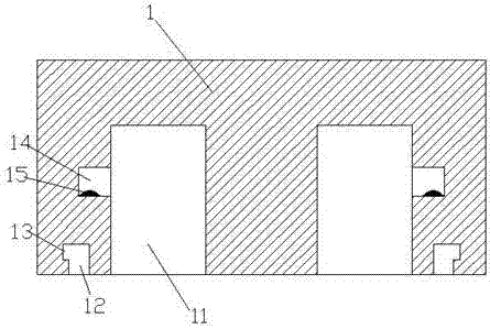
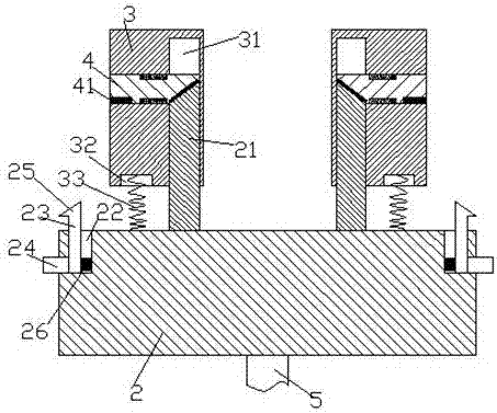
[0018] Combine below Figure 1-5 The present invention will be described in detail.

[0019] refer to Figure 1-5 According to an embodiment of the present invention, a safety plug device for power supply includes a socket body 1 fixedly installed in the wall, a plug body 2 connected to electrical equipment through wires 5, and the socket body 1 is symmetrically arranged left and right There is a slot 11, a power supply slot 14 is arranged in the outer end wall of the slot 11, and a power supply shrapnel 15 is arranged in the front end wall of the power supply slot 14, and locking extensions are arranged symmetrically on the left and right sides of the front end of the socket body 1. Slot 12, the rear end of the locking insertion slot is provided with a locking slot 13 extending to the outer end, the locking insertion slot 12 is located at the outer end of the slot 11; the rear end surface of the plug body 2 is symmetrically provided with power supply The plug, the power sup...


PUM


Abstract

The invention discloses a safety plug device for power supply, and the device comprises a socket body which is fixedly installed in a wall body, and a plug body which is connected with power equipment through a wire. The socket body is provided with slots in a manner of lateral symmetry, and the outer side end walls of the slots are provided with power supply grooves. The front end walls of the power supply grooves are provided with power supply elastic pieces. The front end face of the socket body is provided with locking stretch-in grooves in a manner of lateral symmetry, and the rear ends of the locking stretch-in grooves are provided with locking grooves which extend towards outer side ends. The rear end face of the plug body is provided with power supply pins in a manner of lateral symmetry, and each power supply pin comprises a lead-in block cooperating with the corresponding slot, and a plug bar which is fixedly disposed on the rear end face of the plug body. Each lead-in block is provided with a longitudinal groove and a lateral groove, wherein the opening of the longitudinal groove faces forwards, and the opening of the lateral groove faces an outer side end. The lateral grooves are communicated with the longitudinal grooves. The plug bars stretch into the longitudinal grooves, and the lateral grooves are slidingly provided with telescoping arms. The inner side end of each telescoping arm is provided with an extruding inclined surface and a jacking surface, wherein each extruding inclined surface stretches out of the corresponding lateral groove, and stretches into the corresponding longitudinal groove to abut against an extruding action surface of the rear end of the plug bar.

Description

technical field [0001] The invention relates to the field of electric power supply, in particular to a safety plug-in device for power supply. Background technique [0002] Generally, electrical equipment needs to be powered on before it can work, and the electrical equipment is powered by the cooperation of the plug body and the socket body. The traditional plug and socket use the friction between the two to achieve The state is locked when it is inserted, but this locking method is extremely unstable. When the plug body is accidentally touched or lifted, it is easy to separate or loosen the plug body and the socket body. The equipment is prone to failure, and in the traditional socket, the electric equipment can be powered when the conductive column of the plug is inserted into the socket, but this structure is not safe enough, for example, in the household socket, some young children who lack safety awareness For children, things such as iron rods and keys can be inserte...

Claims


Application Information

Patent Timeline
Patent Type & Authority Applications(China)
IPC IPC(8): H01R13/71H01R13/627H01R13/44
CPCH01R13/71H01R13/44H01R13/6273
Inventor 不公告发明人
Owner 佛山腾谱工业设计有限公司
Why Eureka
Try Eureka