
Line pressing mechanism of full-automatic line cutting and crimping machine

A crimping machine, fully automatic technology, applied in the direction of connection, line/collector parts, electrical components, etc., can solve the problems of low work efficiency, unguaranteed yield rate, damaged wires, etc., and achieve the effect of stable wire joints

Active Publication Date: 2017-11-07
WUHU BOKANG ELECTRICAL
View PDF7 Cites 0 Cited by
  • Summary
  • Abstract
  • Description
  • Claims
  • Application Information

AI Technical Summary

Problems solved by technology

[0002] When wiring, it is necessary to connect the end of the wire to the wire connector. In the past, it was manually operated by hand. After the hole was aligned, it was clamped with a clip. The problem of disconnection, such manual operation, not only the work efficiency is low, the work intensity is high, but the yield rate cannot be guaranteed, it is difficult to meet the needs of customers and the market

Method used


Image

  • Line pressing mechanism of full-automatic line cutting and crimping machine
  • Line pressing mechanism of full-automatic line cutting and crimping machine
  • Line pressing mechanism of full-automatic line cutting and crimping machine

Examples


specific Embodiment approach

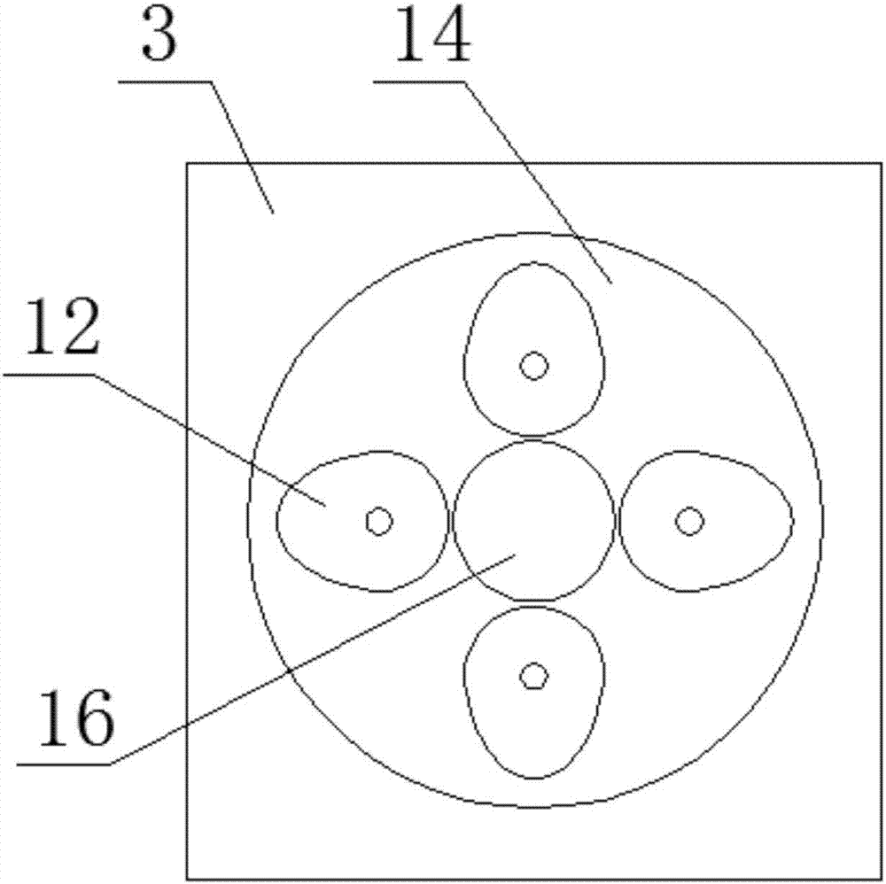
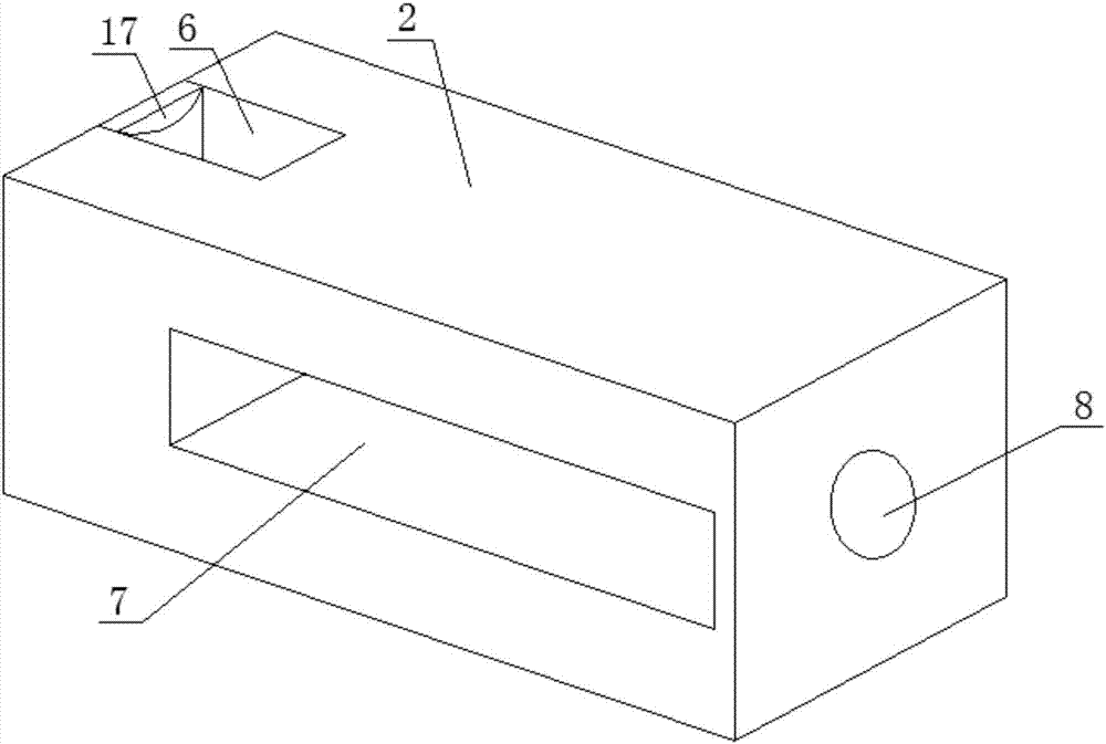
[0018] Figure 1-5 A specific embodiment of the present invention is shown: a fully automatic wire tangential crimping machine crimping mechanism, including a crimping device, a feeding mounting seat 1 and a loading and unloading mounting seat 2, and the feeding mounting seat 1 is provided with a rectangular wire release slot 4 and outlet holes 5, the loading and unloading installation seat 2 is provided with a joint feed chute 6, a horizontal lowering chute 7 and a joint outlet hole 8, and the outer end walls of the feeding installation seat 1 and the loading and unloading installation seat 2 are both A triangular support frame 9 is provided, and a hydraulic cylinder 10 is arranged on the triangular support frame 9, and the telescopic rods of the two hydraulic cylinders 10 respectively pass through the feeding mounting seat 1 and the loading and unloading mounting seat 2 to reach the rectangular pay-off slot 4 and In the joint feeding trough 6, push plates 11 are provided on ...


PUM


Abstract

The invention discloses a line pressing mechanism of a full-automatic line cutting and crimping machine, which comprises a line pressing device, a feeding installation base and a loading / unloading installation base, and is characterized in that the feeding installation base is internally provided with a rectangular line placement groove and a line outlet, the loading / unloading installation base is internally provided with a joint feeding groove, a transverse unloading groove and a joint outlet hole, both the outer end wall of the feeding installation base and the outer end wall of the loading / unloading installation base are provided with a triangular supporting frame, each triangular supporting frame is provided with a hydraulic cylinder thereon, telescopic rods of the two hydraulic cylinders respectively penetrate through the feeding installation base and the loading / unloading installation base to reach the rectangular line placement groove and the joint feeding groove, the telescopic rods of the two hydraulic cylinders are provided with push plates respectively, a line pressing installation base is internally provided with a cylindrical groove, a joint inlet hole and a line inlet, four stepping motors are arranged at the right side of the line pressing installation base, an output shaft of each stepping motor penetrates through the cylindrical groove, and line pressing cams are arranged on the output shafts respectively. The line pressing mechanism is simple in structure, convenient to operate, reasonable in design and capable of realizing automatic production.

Description

technical field [0001] The invention relates to the technical field of wire crimping devices, in particular to a wire crimping mechanism of a fully automatic wire cutting and crimping machine. Background technique [0002] When wiring, it is necessary to connect the end of the wire to the wire connector. In the past, it was manually operated by hand. After the hole was aligned, it was clamped with a clip. The problem of disconnection, such manual operation, not only the work efficiency is low, the work intensity is high, and the yield rate cannot be guaranteed, it is difficult to meet the needs of customers and the market. Contents of the invention [0003] The technical problem to be solved by the present invention is to provide a crimping mechanism of a fully automatic thread tangential crimping machine to solve the above-mentioned multiple defects caused by the prior art. [0004] In order to achieve the above object, the present invention provides the following techni...

Claims


Application Information

Patent Timeline
Patent Type & Authority Applications(China)
IPC IPC(8): H01R43/048H01R43/052
CPCH01R43/048H01R43/052
Inventor 朱磊马能发李华郑凯邱亮亮施其兵方良周前宽张冲张静冯瑞叶立新张建军杨开文
Owner WUHU BOKANG ELECTRICAL
Learn More