Power amplifier capable of suppressing pulling phenomenon

A power amplifier and pulling effect technology, which is applied to power amplifiers, amplifiers, amplifiers with semiconductor devices/discharge tubes, etc., to achieve the effect of reducing frequency pulling effects

Active Publication Date: 2017-11-07
拓尔微电子股份有限公司
View PDF7 Cites 6 Cited by
  • Summary
  • Abstract
  • Description
  • Claims
  • Application Information

AI Technical Summary

Problems solved by technology

[0005] 2) There is no even-order filter capacitor, resulting in a very large secondary current harmonic component on t

Method used


Image

  • Power amplifier capable of suppressing pulling phenomenon
  • Power amplifier capable of suppressing pulling phenomenon
  • Power amplifier capable of suppressing pulling phenomenon

Examples


Embodiment Construction

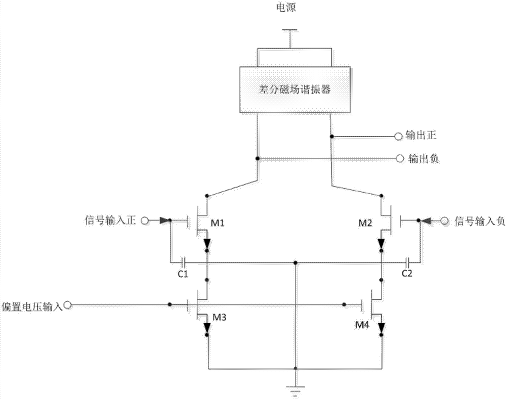
[0016] Attached as follows Figure 2-3 , to further describe the application scheme:

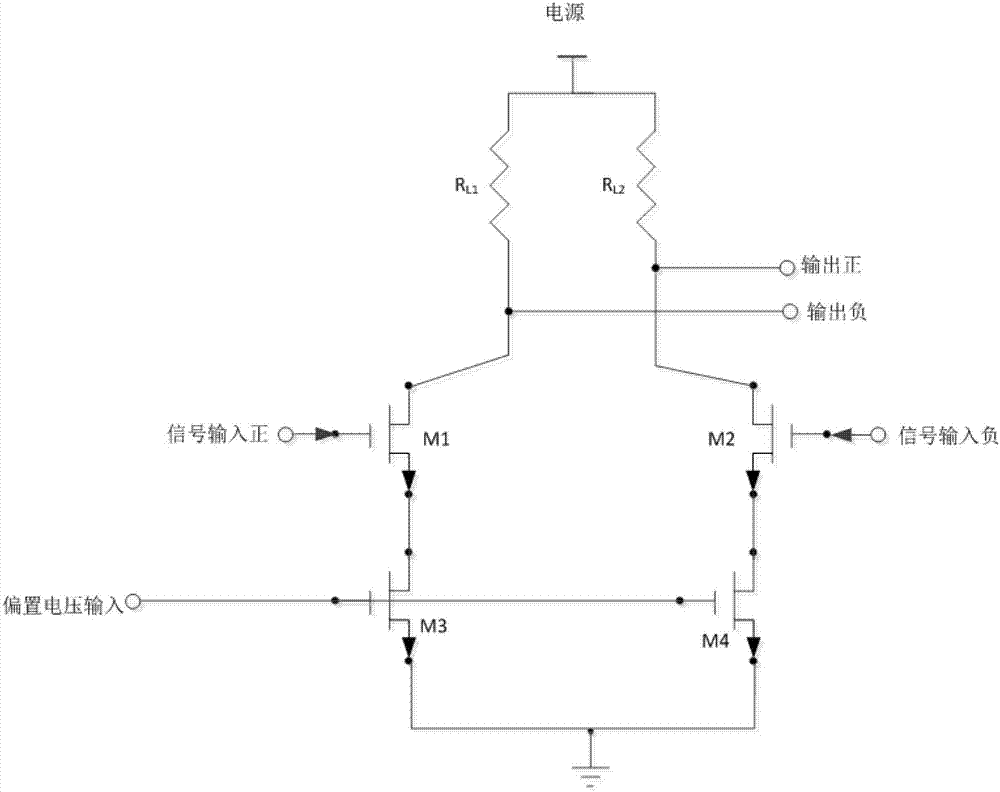
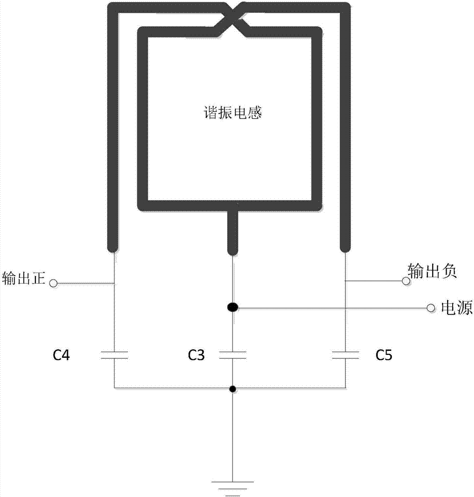
[0017] A power amplifier for suppressing the frequency pulling effect is characterized in that it includes: a differential amplifier tube composed of a combination of transistors M1 and M2, a bias tube composed of a combination of transistors M3 and M4, second-order filter capacitors C1 and C2, and a differential magnetic field resonator;

[0018] The transistor M1 is connected to the transistor M3, and the transistor M2 is connected to the transistor M4; the control pole of the transistor M1 is grounded by the input second-order filter capacitor C1, and is input positive as a signal of the power amplifier; the control pole of the transistor M2 is input by the second-order filter capacitor C1. The filter capacitor C2 is grounded and used as a signal input negative of the power amplifier; the transistors M1 and M2 are respectively connected to the power supply terminal through the differenti...


PUM


Abstract

The invention provides a power amplifier capable of suppressing a pulling phenomenon. The power amplifier comprises a differential amplification tube composed of a transistor M1 and a transistor M2, a biasing tube composed of a transistor M3 and a transistor M4, second-order filter capacitors C1 and C2, and a differential magnetic field resonator, wherein the transistor M1 is connected with the transistor M3, and the transistor M2 is connected with the transistor M4; the control pole of the transistor M1 is earthed via the second-order filter capacitor C1 and serves as positive signal input of the power amplifier; the control pole of the transistor M2 is earthed via the second-order filter capacitor C2 and serves as the negative signal input of the power amplifier; the transistors M1 and M2 are connected with a power end via the differential magnetic field resonator; and the control poles of the transistors M3 and M4 are connected with the input of biasing voltage. According to the power amplifier provided by the invention, the differential magnetic field resonator and the even-order filter capacitors are used, so that second harmonic interference signals generated by the power amplifier can be greatly suppressed, and thus frequency pulling effect on a direct up-conversion transmitter is reduced.

Description

technical field [0001] The invention relates to a power amplifier suppressing the frequency pulling effect. Background technique [0002] The direct up-conversion transmitter has been widely used in integrated circuits because of its simple structure and easy implementation. However, since the frequency of the phase-locked loop (PLL) in the direct up-conversion transmitter is the same as the frequency of the final transmitted signal, this causes the transmitted signal to interfere with the phase-locked loop, and the interference signal enters the transmitter again through the PLL , resulting in spectral regrowth effects that deteriorate the quality of the transmitted signal. The power amplifier is an important part of the direct up-conversion transmitter, which plays the role of amplifying and transmitting the signal, and its inherent second harmonic is an important cause of frequency pulling. [0003] Currently used power amplifiers (refer to attached figure 1 ) The ampl...

Claims


Application Information

Patent Timeline
IPC IPC(8): H03F1/26H03F3/24H04B1/04
CPCH03F1/26H03F3/245H04B1/04H04B1/0475H04B2001/0408
Inventor 王昭陈弟虎郭建平
Owner 拓尔微电子股份有限公司
Why Eureka
Try Eureka