3D display device and method

A technology for a display device and an LED display, applied in the field of 3D display, can solve problems such as poor 3D effect, achieve the effect of improving stereoscopic effect, large viewing angle, and improving monocular resolution

Pending Publication Date: 2017-11-10
北京虚拟动点科技有限公司
View PDF6 Cites 9 Cited by
  • Summary
  • Abstract
  • Description
  • Claims
  • Application Information

AI Technical Summary

Problems solved by technology

[0007] Embodiments of the present invention provide a 3D display device and method to at least solve the technical problem of poor 3D effect in the prior art

Method used


Image

  • 3D display device and method
  • 3D display device and method
  • 3D display device and method

Examples


Embodiment 1

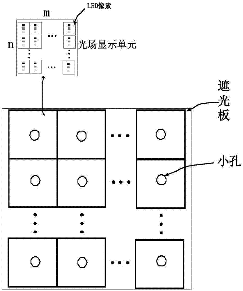
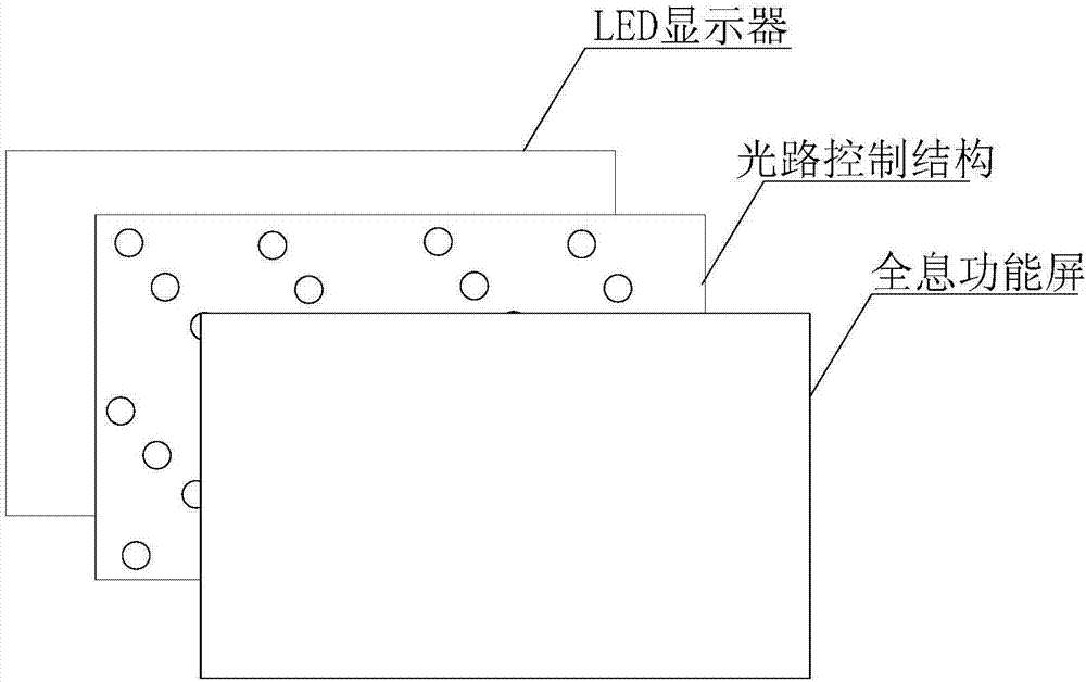
[0059] According to an embodiment of the present invention, a product embodiment of a 3D display device is provided, image 3 is a 3D display device according to an embodiment of the present invention, such as image 3 As shown, the device includes sequentially arranged: an LED display for displaying images; an optical path control structure including a multi-layer pinhole structure for controlling the outgoing direction of the optical path of the image to form three-dimensional light field information, wherein each layer of pinholes Multiple groups of pinhole arrays are arranged on the hole structure; and a holographic functional screen is used for diffuse imaging of three-dimensional light field information to form a 3D image.

[0060] Specifically, in the application of large-size displays such as LED displays, the viewer's viewing distance is generally 5 meters away, and the observer's movement range in the vertical direction is quite limited, so the vertical distance that...

Embodiment 2

[0104] According to an embodiment of the present invention, a method embodiment of a 3D display method is provided. It should be noted that the steps shown in the flow chart of the accompanying drawings can be executed in a computer system such as a set of computer-executable instructions, and, Although a logical order is shown in the flowcharts, in some cases the steps shown or described may be performed in an order different from that shown or described herein.

[0105] Figure 9 is a 3D display method according to an embodiment of the present invention, applied to the above-mentioned 3D display device, such as Figure 9 As shown, the method includes the following steps:

[0106] Step S102, displaying an image through an LED display;

[0107] Step S104, controlling the outgoing direction of the optical path of the image through the optical path control structure of the multi-layer pinhole structure to form three-dimensional light field information, wherein each layer of th...


PUM


Abstract

The invention discloses a 3D display device and a method. The device comprises an LED (light emitting diode) display used for displaying an image; a light path control structure of a multi-layer pinhole structure and used for controlling the light path emergent direction of the image so as to form the three-dimensional light field information; and a holographic function screen used for carrying out diffusion imaging on the three-dimensional light field information to form a 3D image. The LED display, the light path control structure and the holographic function screen are arranged in sequence. Each layer of the pinhole structure is provided with a plurality of groups of pinhole arrays. According to the invention, the technical problem of poor 3D effect in the prior art is solved.

Description

technical field [0001] The present invention relates to the field of 3D display, in particular to a 3D display device and method. Background technique [0002] The 3D light field display technology is considered to be one of the most promising technologies in the field of 3D display because it can realize a real and remarkable naked-eye 3D display effect and can process imaging in real time. [0003] At present, the structure of the display device based on the light field display technology of the common display is as follows: figure 1 shown. The basic principle is based on a shading plate with a small hole and an ordinary display. The image displayed in the display can be encoded by a computer to obtain a light field display unit with m×n resolution, and then the light field display unit can be controlled by using the opening of the shading plate. The direction and intensity of each light emitted by the unit, that is, an array of light field display units modulated by enc...

Claims


Application Information

Patent Timeline
Patent Type & Authority Applications(China)
IPC IPC(8): G02B27/22
CPCG02B30/36H04N13/351G03H1/0465G03H1/2205G03H2001/0212G03H2001/0473G03H2001/2213
Inventor 卢长军王治昊杨乐刘博阳
Owner 北京虚拟动点科技有限公司
Why Eureka
Try Eureka