Power knife turret protection structure, power knife turret system and control method

A technology of power turret and protective structure, which is applied in the direction of manufacturing tools, clamping, support, etc., can solve the problems of turret displacement error, reduce reliability, wear and other problems, and achieve stable structure operation, high precision, and efficient switching and rotation Effect

Pending Publication Date: 2017-11-17
WENLING SANHE CNCEQUIP
View PDF1 Cites 5 Cited by
  • Summary
  • Abstract
  • Description
  • Claims
  • Application Information

AI Technical Summary

Problems solved by technology

[0005] The reliability of the turret is not high, and the turret may have displacement errors during the tool change process. Ordinary locking or positioning structures cannot effectively feedback the internal conditions of the equipment. If displacement errors occur, it is not easy to find them. It is laborious, and after a long period of equipment use, it may cause internal wear and tear caused by the tool change action of the cutter head, thereby reducing reliability

Method used


Image

  • Power knife turret protection structure, power knife turret system and control method
  • Power knife turret protection structure, power knife turret system and control method
  • Power knife turret protection structure, power knife turret system and control method

Examples


Embodiment 1

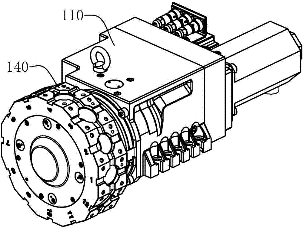
[0044] Such as figure 1 As shown, this is the overall structure of the power turret, which includes a turret body 110 and a cutter head 140, the turret body 110 and the cutter head 140 can rotate relatively, and the turret body 110 is fixed on the equipment.

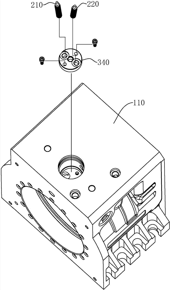
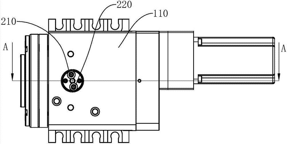
[0045] Such as figure 2 As shown, an installation cavity is opened on the turret body 110, in which the first proximity switch 210, the second proximity switch 220 and the positioning plate 340 are assembled. The positioning plate 340 is fixed on the turret body 110 by bolts.

[0046] to combine image 3 and Figure 4 , the following describes the internal structure of the turret body 110 and the gist of the invention.

[0047] A power turret protection structure further includes a turret body 110 , a first transmission shaft 120 , a movable toothed plate 130 , a double chained plate 150 and a thrust spring 160 . Figure 4 Among them, the driving source may be a transmission gear device 500, which is connected to the...

Embodiment 2

[0058] Such as Figure 6 As shown, a power turret system includes the above-mentioned power turret protection structure, and also includes a hydraulic mechanism 410 , a servo motor 420 , a controller 430 and a power supply 440 . The servo motor 420 is used to drive the first transmission shaft 120 to rotate. The first proximity switch 210 , the second proximity switch 220 , the hydraulic mechanism 410 , and the servo motor 420 are connected to a controller 430 . The forward position of the distance between the first proximity switch 210 and the second proximity switch 220 and the middle part of the double chainring 150 from the through ring groove 190 changes. Thereby, the stroke of the duplex chainring 150 can be detected.

[0059] The controller 430 does not receive the signal of the first proximity switch 210 and receives the signal of the second proximity switch 220 to output a locking signal, and the locking signal is specifically a level signal.

[0060] The controller...


PUM


Abstract

The invention discloses a power knife turret protection structure, a power knife turret system and a control method, and aims to provide the power knife turret which is highly-reliable and safe and stable in operation. The technical scheme of the invention is characterized in that safe locking is performed through a duplex fluted disc, a static gear ring and a movable fluted disc structure; reliability is improved through a pushing spring; a piston-type unlocking function is formed by utilizing an oil cavity; and working stability and reliability are improved by adopting a sealing ring.

Description

technical field [0001] The invention relates to the technical field of power turrets, in particular to a power turret protection structure, a power turret system and a control method. Background technique [0002] In the prior art, such as the patent application publication number CN104827066A, its technology discloses a hydraulic power turret, the cutterhead is used for installing various cutters, the cutterhead is driven by the transmission spindle, and the cutterhead can be rotated , to switch between different tools. [0003] When the power turret cutter head stops rotating, it needs to maintain a stable position to avoid position deviation during tool processing. [0004] To realize tool switching, the cutter head has a degree of freedom, and this degree of freedom needs to be restricted when the tool is being processed. Thus, a locking scheme for the cutter head is proposed. There are following disadvantages in the existing locking structure: [0005] The reliabili...

Claims


Application Information

Patent Timeline
IPC IPC(8): B23B29/32B23Q3/157
CPCB23B29/32B23Q3/157Y02P70/10
Inventor 林坚勇
Owner WENLING SANHE CNCEQUIP
Why Eureka
Try Eureka