
Reciprocating rod conveyor line

A technology of reciprocating rod and conveying line, applied in the field of reciprocating rod conveying line, can solve problems such as workpiece deformation, and achieve the effect of avoiding deformation and improving conveying rhythm.

Active Publication Date: 2019-05-10
DONGFENG LIUZHOU MOTOR
View PDF8 Cites 0 Cited by
  • Summary
  • Abstract
  • Description
  • Claims
  • Application Information

AI Technical Summary

Problems solved by technology

[0003] The problem to be solved by the present invention is to provide a multi-link reciprocating rod conveying line to solve the problem that the existing reciprocating rod conveying line with four-link lifting unit easily causes workpiece deformation

Method used


Image

  • Reciprocating rod conveyor line
  • Reciprocating rod conveyor line
  • Reciprocating rod conveyor line

Examples


Embodiment 1

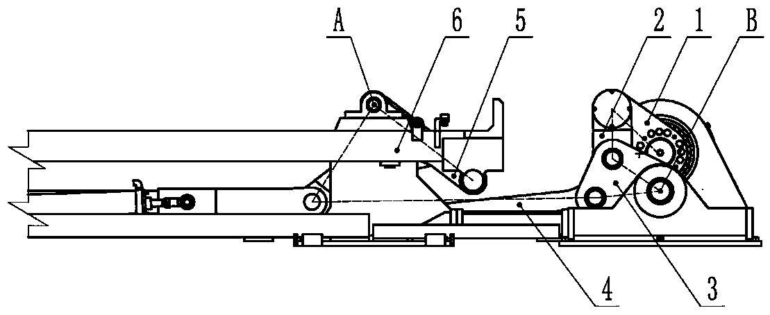
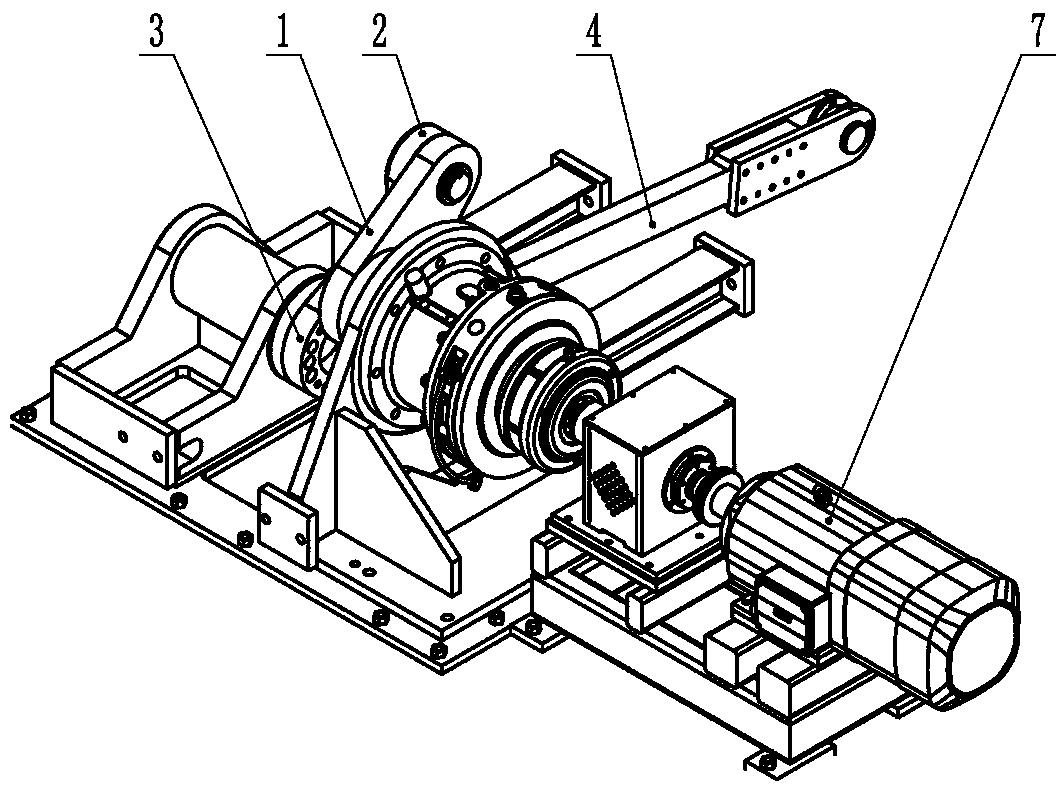
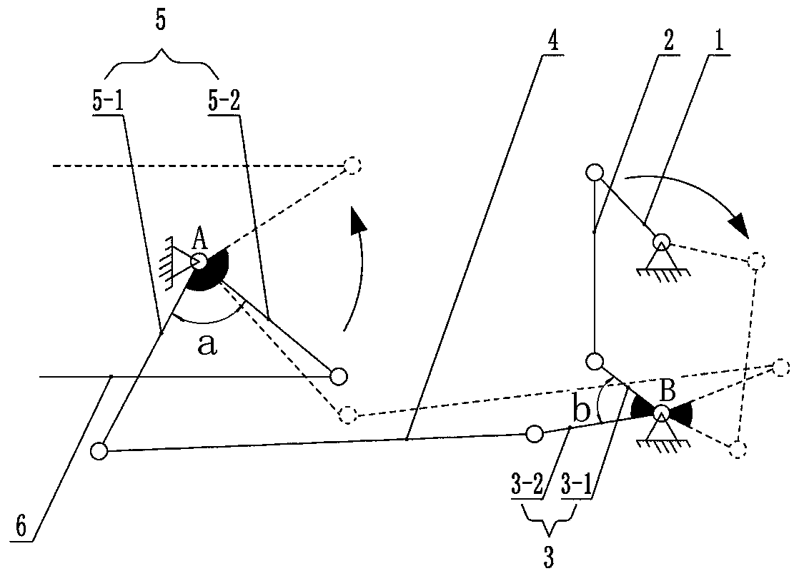
[0014] Such as figure 1 , figure 2 and image 3 The shown reciprocating rod conveying line includes a reciprocating rod bracket 6, and the reciprocating rod bracket 6 is connected to the drive motor 7 through a multi-link lifting unit. The multi-link lifting unit in this embodiment is a six-link lifting unit; The connecting rod lifting unit includes a swing arm 1 arranged on the output shaft of the drive motor 7, one end of the swing arm 1 is set on the output shaft of the drive motor 7 through an expansion sleeve, and the other end of the swing arm 1 is connected by a roller bearing and a short pull rod. One end of 2 is hinged; the other end of the short pull rod 2 is hinged with one end of the upper triangular link 3-1 of the triangular connecting rod 3 through an outer spherical roller bearing, and the triangular connecting rod 3 includes one end hinged on the hinge shaft IIB at an angle b The set triangle upper link 3-1 and the triangle lower link 3-2, the angle b betwe...

Embodiment 2

[0016] The angle b between the triangle upper link 3-1 and the triangle lower link 3-2 is 35°, the angle a between the lift lower link 5-1 and the lift upper link 5-2 is 65°, and the other features Same as Example 1.

Embodiment 3

[0018] The angle b between the triangle upper link 3-1 and the triangle lower link 3-2 is 45°, the angle a between the lift lower link 5-1 and the lift upper link 5-2 is 75°, and the other features Same as Example 1.

[0019] When working, the workpiece is placed on the process positioning, and the drive motor 7 rotates forward at a uniform speed to drive the swing arm 1, the swing arm 1 drives the short tie rod 2, the short tie rod 2 drives the triangular connecting rod 3, and the triangular connecting rod 3 drives the long pull rod 4, and The lifting swing arm 5 connected with the long pull rod 4 drives the reciprocating rod bracket 6 to perform a vertical variable-speed upward movement. When the reciprocating rod bracket 6 rises to 200mm, it contacts the workpiece. workpiece, so that the impact on the workpiece is small, the reciprocating rod bracket 6 will accelerate the movement after contacting the workpiece, and improve the conveying rhythm. When the workpiece is trans...


PUM


Abstract

The invention discloses a reciprocating lever conveyor line and relates to the technical field of automobile making. The reciprocating lever conveyor line comprises a reciprocating lever bracket. The reciprocating lever bracket is connected with a driving motor through a multi-connecting-rod lifting unit. The multi-connecting-rod lifting unit comprises a swing arm arranged on an output shaft of the driving motor. The swing arm is hinged to a triangle connecting rod through a short pull rod. The triangle connecting rod is hinged to a lifting swing arm through a long pull rod. The lifting swing arm comprises a lower lifting connecting rod and an upper lifting connecting rod which are hinged to a hinged shaft I in an angled mode. The upper lifting connecting rod is hinged to the reciprocating lever bracket. The triangle connecting rod comprises an upper triangle connecting rod and a lower triangle connecting rod which are hinged to a hinged shaft II in an angled mode. The lower triangle connecting rod is hinged to the long pull rod. The upper triangle connecting rod is hinged to the short pull rod. Compared with the prior art, the reciprocating lever conveyor line can solve the problem that an existing reciprocating lever conveyor line with a four-connecting-rod lifting unit is likely to cause deformation of workpieces.

Description

technical field [0001] The invention relates to the technical field of automobile manufacturing, in particular to a reciprocating rod conveying line used for lifting and lowering vehicle body assemblies. Background technique [0002] With the rapid development of the national automobile industry, the production capacity of the whole vehicle factory has also doubled. In the past, the welding line of about 20JPH could not meet the production demand, and a higher beat requirement was put forward for the reciprocating rod conveyor. At present, the more common The design beat is 40JPH, even up to 60JPH. The hydraulically driven lifting mechanism cannot meet such a high speed requirement. Therefore, a four-link lifting unit driven by a motor is adopted, and its lifting action can be completed within 6 seconds. Compared with the previous hydraulic The speed of the drive mechanism has been doubled. There is a reciprocating rod conveyor line that includes a reciprocating rod bracket...

Claims


Application Information

Patent Timeline
Patent Type & Authority Patents(China)
IPC IPC(8): B65G47/74
CPCB65G47/74
Inventor 周海斌黄佳华文建东黄初敏李昆霖
Owner DONGFENG LIUZHOU MOTOR
Learn More