Mechanical sealing device for high-speed sand mill

A mechanical seal device and sand mill technology, which is applied in the direction of engine seals, mechanical equipment, engine components, etc., can solve the problem of short service life of unbalanced mechanical seals, easy damage of seal end faces, and inability to be used in high-speed rotary conditions, etc. problems, to achieve the effect of strong sealing adaptability, stable liquid film and long service life

Pending Publication Date: 2017-11-17
西安普力流体科技有限公司
View PDF8 Cites 1 Cited by
  • Summary
  • Abstract
  • Description
  • Claims
  • Application Information

AI Technical Summary

Problems solved by technology

[0010] In order to solve the technical problems in the prior art that the unbalanced mechanical seal has a short service life, cannot be used

Method used


Image

  • Mechanical sealing device for high-speed sand mill
  • Mechanical sealing device for high-speed sand mill
  • Mechanical sealing device for high-speed sand mill

Examples


Example Embodiment

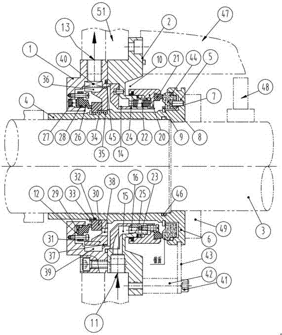
[0063] In order to further illustrate the technical means and effects adopted by the present invention to achieve the predetermined purpose, the specific embodiments, structural features and effects of the present invention will be described in detail below with reference to the accompanying drawings and examples.

[0064] In the description of the invention, it should be understood that the terms "center", "vertical", "horizontal", "upper", "lower", "front", "rear", "left", "right", The orientation or positional relationship indicated by "vertical", "horizontal", "top", "bottom", "inner", "outer", etc. is based on the orientation or positional relationship shown in the drawings, and is only for the convenience of describing the present invention The creation and simplification of the description does not indicate or imply that the pointed device or element must have a specific orientation, be constructed and operated in a specific orientation, and therefore cannot be understood a...


PUM


Abstract

The invention relates to a mechanical sealing device for a high-speed sand mill. The mechanical sealing device comprises an outer gland, an inner gland and a shaft sleeve. The shaft sleeve is sleeved with the outer gland and the inner gland. The outer gland and the inner gland are connected through a screw. An inner movable ring is arranged at the right end of the shaft sleeve. The right end of the inner gland is sleeved with an inner static ring assembly. The right end face of the inner static ring assembly is in fit with the left end face of the inner movable ring, and a main seal is formed. An inner movable ring assembly with which the shaft sleeve is sleeved is arranged in the gap between the shaft sleeve and the outer gland. The outer gland is provided with an outer static ring assembly. The left end face of the outer movable ring assembly is in fit with the right end face of the outer static ring assembly, and therefore a safe seal is formed. An isolation sleeve is arranged in the gap among the inner gland, the outer gland and the shaft sleeve. A sealing cavity is formed between the isolation sleeve and the inner gland and communicates with a liquid feeding hole, the sealing cavity communicates with an overflowing hole inside the inner gland, and therefore a liquid loop is formed. The mechanical sealing device is used for a device which is rotated at a high speed, a sealing end face is not likely to be damaged, and the service life is longer.

Description

technical field [0001] The invention belongs to the technical field of mechanical seals, and in particular relates to a mechanical seal device for high-speed sand mills. Background technique [0002] Sand mills are widely used in stirring and grinding operations in food, petrochemical, emulsification, paint and other industries. The traditional seals are packing, single-end or double-end spring-type mechanical seals. Especially in the field of nano-scale materials for new energy, the sand mill industry is developing rapidly. With the improvement of technology and output requirements, various manufacturers have successively developed sand mill products with a rotating speed of 3000rpm~15000rpm, but limited by the existing mechanical seal technology used, the test operation effect of new products is not ideal, mainly as follows question: [0003] 1. At present, the mechanical seals used for sand mills generally use unbalanced mechanical seals. The reason for using them is th...

Claims


Application Information

Patent Timeline
IPC IPC(8): F16J15/34F16J15/40
CPCF16J15/162F16J15/34F16J15/3452F16J15/40
Inventor 郭文德叶俊杰陈君应
Owner 西安普力流体科技有限公司
Why Eureka
Try Eureka