Sealing component and rotary kiln sealing component

A technology for sealing components and rotary kilns, which is applied to the sealing of engines, rotary drum furnaces, engine components, etc., and can solve the problems of poor sealing, inability to adapt to the deformation of rotating parts, and large air leakage gaps.

Active Publication Date: 2013-04-03
高玉宗
View PDF10 Cites 8 Cited by
  • Summary
  • Abstract
  • Description
  • Claims
  • Application Information

AI Technical Summary

Problems solved by technology

[0004] In order to solve the problems of large air leakage gaps, inability to adapt to the deformation of the rotary parts and poor sealing performance of the sealing components used to seal the connection between the fixed part and the rotary part in the prior art, especially the kiln head seal component and the kiln tail seal component of the rotary kiln , the present invention provides a sealing assembly and a rotary kiln sealing assembly, its unique structural design can control the air leakage gap to be small and can adapt to the deformation of the rotary parts, effectively improving the sealing effect

Method used


Image

  • Sealing component and rotary kiln sealing component
  • Sealing component and rotary kiln sealing component
  • Sealing component and rotary kiln sealing component

Examples


Embodiment 1

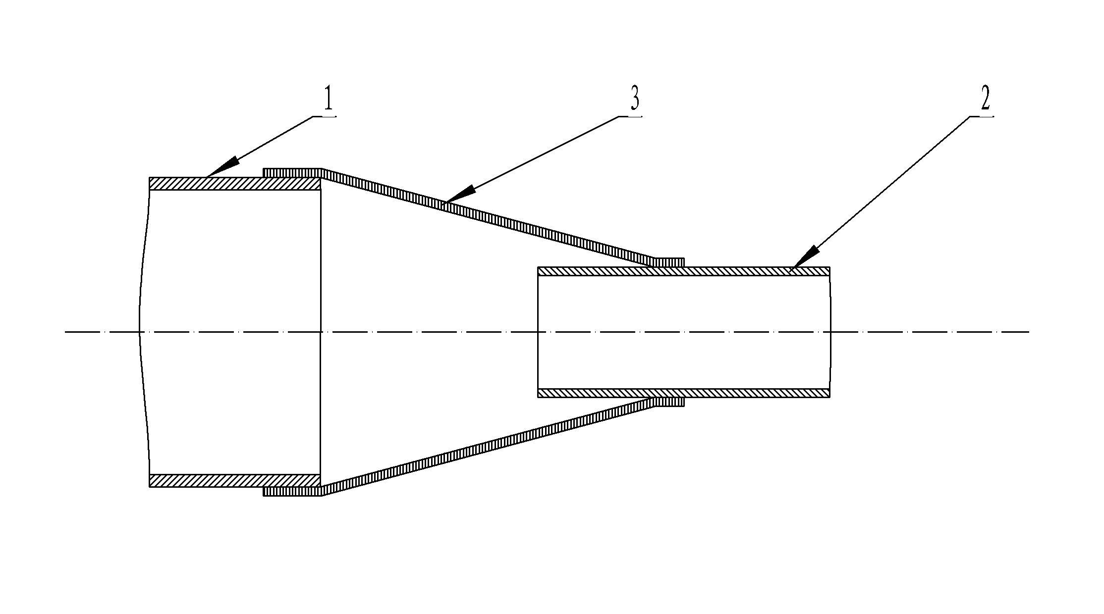
[0038] Such as figure 1 Shown is a schematic structural view of the first embodiment of the sealing assembly of the present invention. The figure shows the fixed part 1 and the cylindrical rotating part 2 of the hollow structure, and the sealing body 3 used for sealingly connecting the fixed part 1 and the rotating part 2 (the sealing assembly in this embodiment is the sealing body 3), wherein the sealing The front open end (large open end) of body 3 is fixed (preferably, sealed and fixed) on the rear open end of fixed part 1, makes sealing body 3 and the inner chamber of fixed part 1 communicate; (Small opening end) is set on the outer wall of the rotary part 2, that is, the inner side of the rear open end of the sealing body 3 is connected with the outer wall of the rotary part 2, so that the sealing body 3 and the inner cavity of the rotary part 2 are connected, when the rotary part 2 When rotating, the inner side of the rear opening end of the sealing body 3 and the outer...

Embodiment 2

[0043] Figure 4 As shown, it is another embodiment of the sealing assembly. The difference between this embodiment and Embodiment 1 is:

[0044] The diameter of the rear end surface of the fixed part 1 in Embodiment 1 is greater than the diameter of the front end surface of the rotary part 2, while the diameter of the rear end surface of the fixed part 1 in this embodiment is smaller than the diameter of the front end surface of the rotary part 2. At this time, the diameter of the rear open end is adopted. The sealing body 3 whose diameter is greater than the diameter of the front opening end (the sealing assembly of the present embodiment is the sealing body 3), so that the rear opening end of the sealing body 3 is compatible with the front opening end of the rotary part 2 and the front opening end of the sealing body It is suitable for the rear open end of the fixed part 1.

[0045] Preferably, in the case of this embodiment, in order to make the rear open end of the seali...

Embodiment 3

[0047] Figure 5 It is a structural schematic diagram of the third embodiment of the seal assembly used between the fixed part and the rotating part. The difference between this embodiment and embodiment 1 is:

[0048] The sealing assembly in this embodiment (see Figure 5 ) also includes a hollow revolving body structure of the tapered support 4, the tapered support 4 is fixedly connected (also can adopt the sealing and fixed connection mode of welding) on ​​the fixed part 1, the tapered support 4 can also be connected with the fixed part 1 Integral structure, the tapered support 4 plays the role of connecting the fixed part 1 and the sealing body 3, through the transition connection of the tapered support 4, the setting of the sealing body 3 is more flexible, and the support 4 of different structures can be used To change the relative relationship between the sealing body 3 and the rotating part 2. For example: when the diameter of the end face of the fixed part 1 is small...


PUM


Abstract

The invention provides a sealing component, which is used for sealing connection between a hollow fixing part and a tubular rotary part. The sealing component comprises a tubular sealing body. One open end of the sealing body is fixedly connected with the fixing part, and is used for communicating an inner cavity of the sealing body with an inner cavity of the fixing part. The other open end of the sealing body is sleeved on the outer wall of the rotary part, and is used for communicating the inner cavity of the sealing body with an inner cavity of the rotary part. The sealing body has a three-layer structure, each of an inner layer and an outer layer consists of a plurality of annularly distributed plates, gaps are reserved between adjacent plates of the inner layer as well as between adjacent plates of the outer layer, and an intermediate layer made from a flexible sealing material is arranged between the inner and outer layers. The inner sides of the plates of the inner layer at the other open end of the sealing body are connected with the outer wall of the rotary part. By the unique structural design of the sealing component, air leakage gaps can be controlled to be small and adapted to the deformation of the rotary part, so that a sealing effect is effectively improved.

Description

technical field [0001] The invention belongs to the technical field of sealing, in particular to a sealing assembly used for sealing between a fixed part and a rotary part, and a rotary kiln sealing assembly used for sealing a kiln head and a kiln tail of a rotary kiln. Background technique [0002] In the prior art, the sealing between the fixed part and the rotating part becomes complicated due to the relative movement between the two parts, especially when there is a gap between the two parts, and there is a pressure difference or temperature difference between the two parts, it will inevitably lead to external Leakage of gas and / or leakage of internal gas. In addition, the bending deformation of the rotating parts during use and the deviation of the center of the cantilever end where the deflection occurs from the center of rotation are unavoidable. The distance of the deviation is called the eccentricity e, and the larger the eccentricity e, the larger the gap will be. ...

Claims


Application Information

Patent Timeline
Patent Type & Authority Applications(China)
IPC IPC(8): F16J15/16F27B7/24
Inventor 高玉宗
Owner 高玉宗
Why Eureka
Try Eureka