
Five-point cylindricity error separation measuring method
A technology of cylindricity error and measurement method, applied in measurement devices, instruments, etc., can solve problems such as difficulty in adapting to online measurement requirements and high cost of instruments
Patent Information
- Authority / Receiving Office
- CN · China
- Patent Type
- Applications(China)
- Current Assignee / Owner
- Publication Date
- 2017-11-17
Smart Images
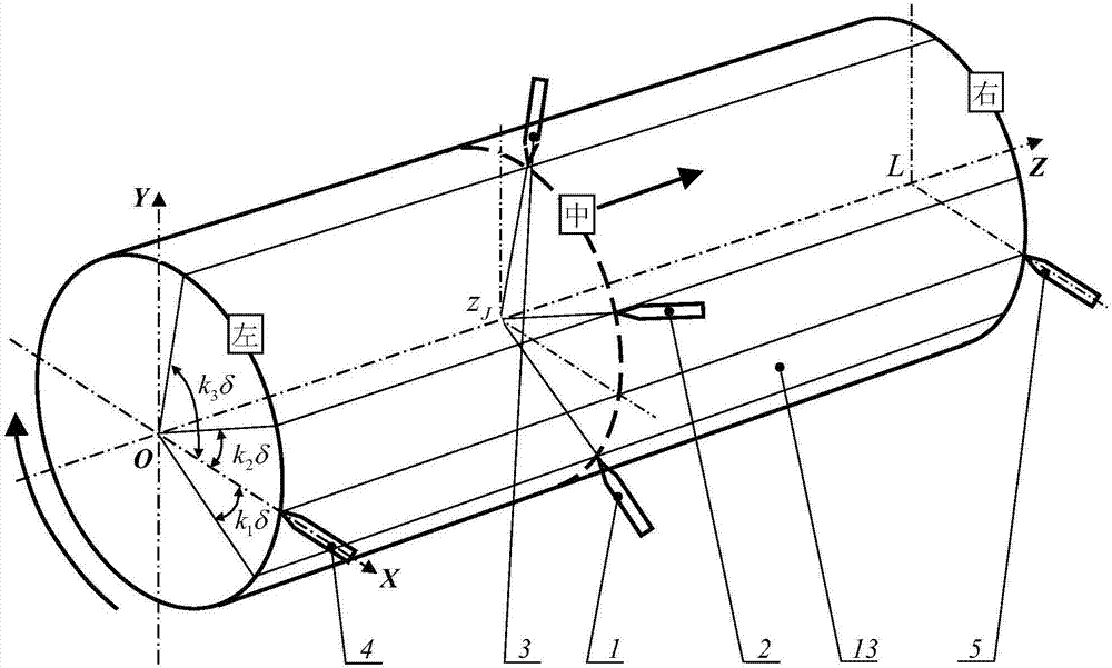
Figure 1 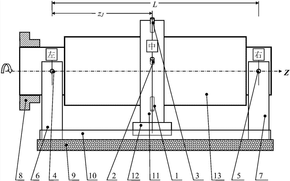
Figure 2 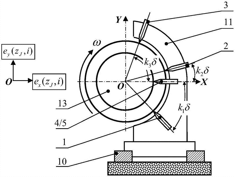
Figure 3
Abstract
Description
technical field
[0001] The invention relates to the field of precision testing technology and the design and manufacture of large-scale online measurement equipment, and is an error separation measurement method for measuring shape errors of cylindrical surface shapes including cylindricity, bus straightness and taper. Background technique
[0002] Precision shaft roller (cylindrical) is the core component of equipment for the production of solar panels, LCD screens, automotive steel plates, high-quality paper, and industrial composite panels. etc. will be copied to the product, causing product surface quality problems. Therefore, how to measure the shape error such as the cylindricity of the precision shaft roller is a technical problem to be solved urgently in the equipment manufacturing industry. In principle, the cylindricity measurement system must involve the rotary shaft system and the linear motion guide rail. The traditional cylindricity measuring instrument is equ...
Examples
Embodiment Construction
[0042] In this example, if figure 2 and image 3 As shown, the left frame 6 and the right frame 7 are fixed at both ends of the measured body 13, on which the fourth sensor 4 and the fifth sensor 5 are installed respectively, to sense the X-direction radial displacement of the cross-section at the left and right ends of the measured body 13 , the axial distance between the fourth sensor 4 and the fifth sensor 5 is L; the center frame 11 is supported on the mobile platform 12, and the mobile platform 12 is supported by the Z guide rail 10 and drives the center frame 11 to move along the Z direction , the Z guide rail 10 is parallel to the axial direction of the measured body 13, so that the moving step distance of the middle measuring frame 11 along the Z direction is d, and the middle measuring frame 11 is provided with a middle section perpendicular to the axial direction of the measured body 13. The first sensor 1 to the third sensor 3 are installed on it to sense the radi...