Axial circular runout and total runout single displacement error separation device and method

A technology of error separation and circular runout, applied in the direction of measuring devices, instruments, etc., can solve the problems that cannot be separated from the axis rotation error of the instrument, the parallelism error of the instrument guide rail to the rotary axis, and cannot meet the ultra-precision circular runout and full runout measurement.

Inactive Publication Date: 2012-04-25
BEIJING INSTITUTE OF TECHNOLOGYGY
View PDF3 Cites 26 Cited by
  • Summary
  • Abstract
  • Description
  • Claims
  • Application Information

AI Technical Summary

Problems solved by technology

However, this method only corrects the error caused by the misalignment of the datum, and cannot separate the rotation error of the instrument shaft system, the parallelism error of the instrument guide rail to the rotation axis, etc.
[0007] The above measurement methods are only suitable for specific end face circular runout measurement, and the error separation method can only separate the axial movement of the rotary spindle or the eccentricity error of the measurement reference to the design reference, which cannot meet the requirements of ultra-precision circular runout and full runout measurement

Method used


Image

  • Axial circular runout and total runout single displacement error separation device and method
  • Axial circular runout and total runout single displacement error separation device and method
  • Axial circular runout and total runout single displacement error separation device and method

Examples


Embodiment 1

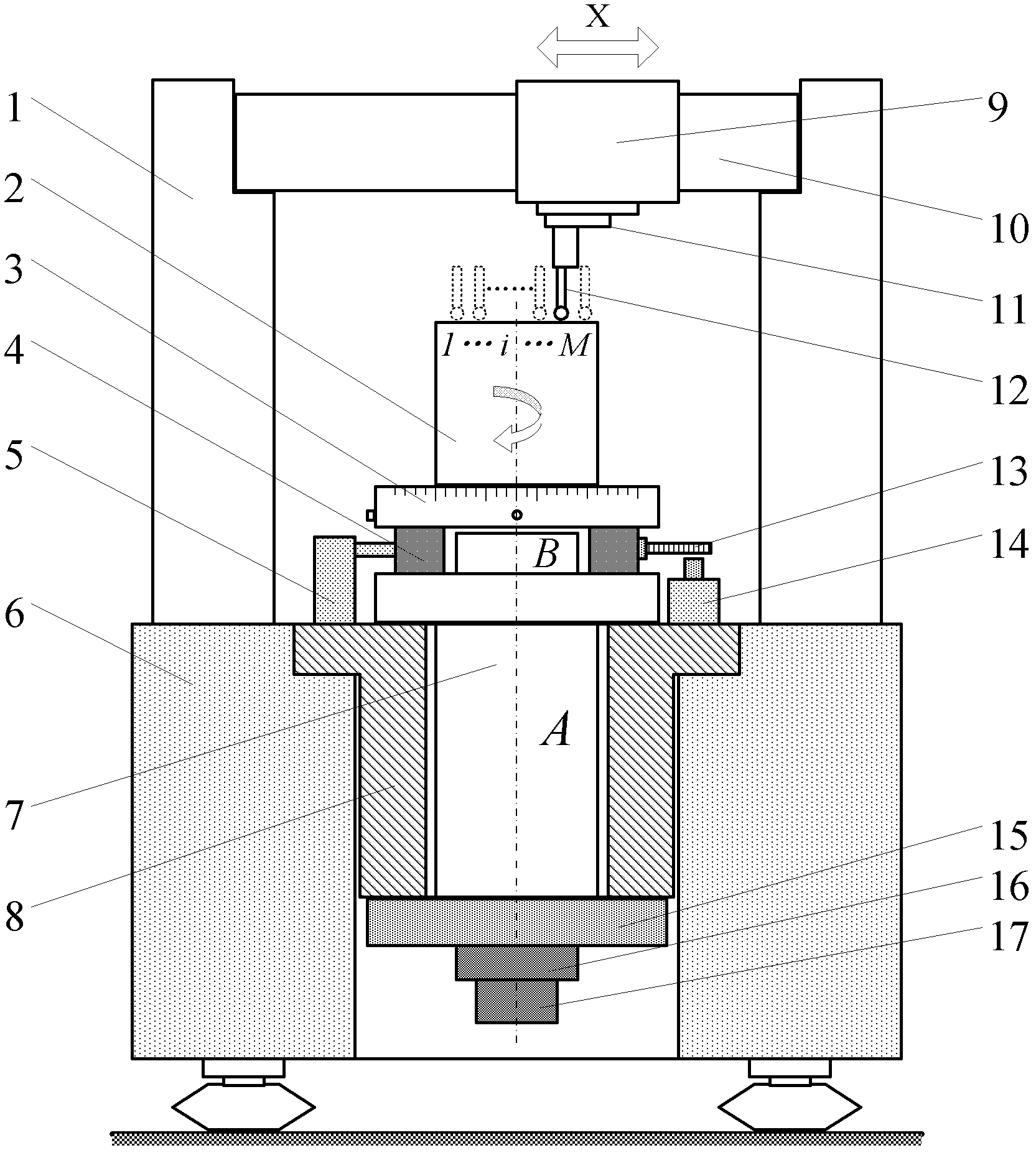
[0072] Taking the axial circular runout measuring instrument in which the spindle of the instrument rotates to drive the workpiece to rotate as an example, the method and specific steps of separating the spindle rotation error z(n) and the workpiece circular runout error g(n) are explained.

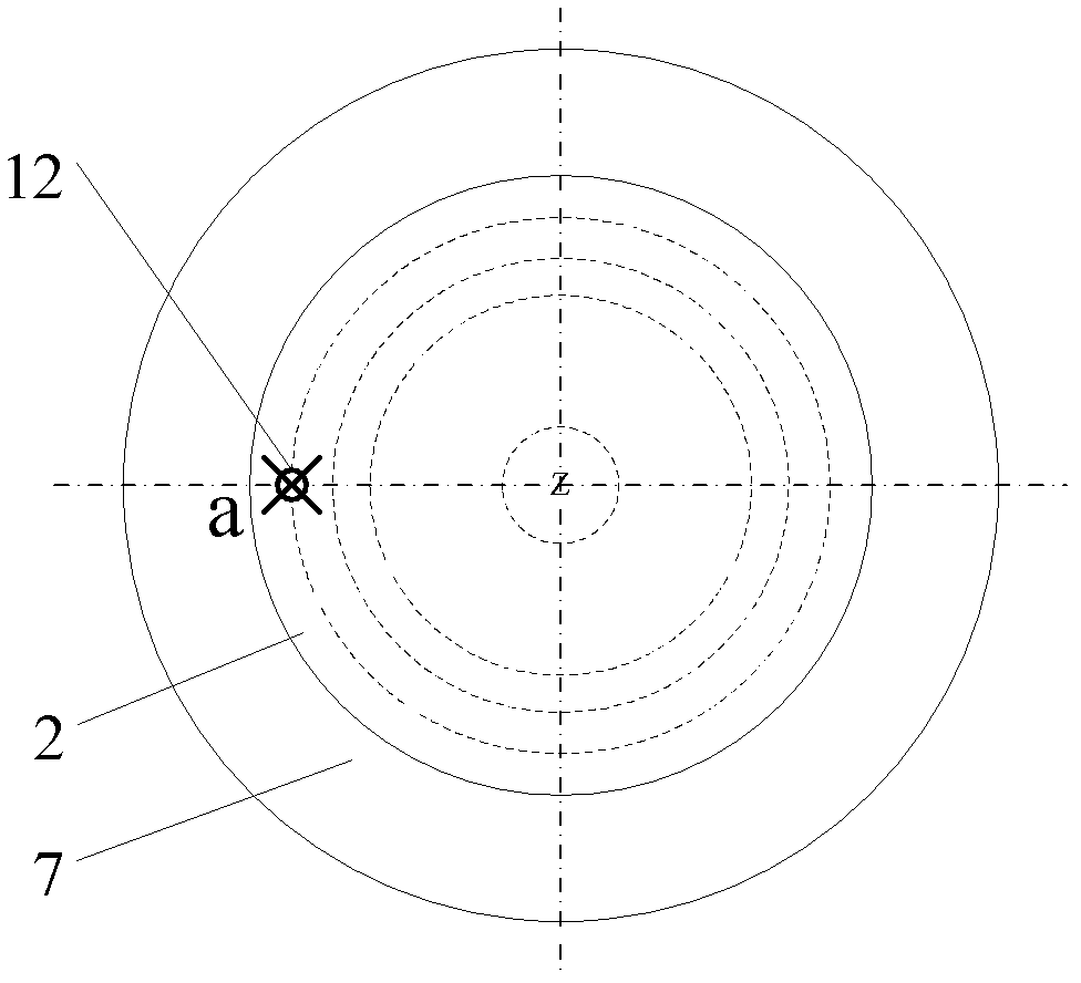
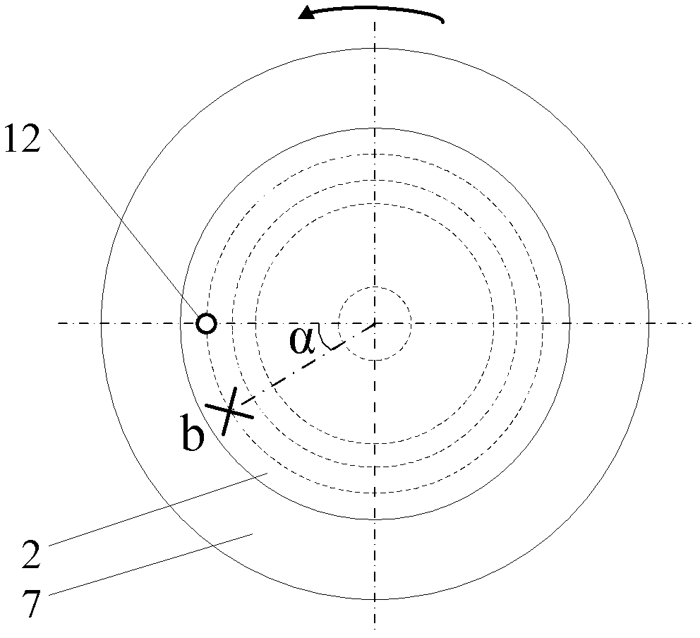
[0073] When actually measuring the circular jump or the full jump, a certain fixed position a on the rotary spindle 7 of the instrument is used as the starting point of the instrument measurement, the workpiece 2 to be measured is located on the rotary table 3, and the starting reference point of the workpiece is b. When the measurement sensor 12 is located on the workpiece 2 such as figure 2 When the first measurement circle 1 is shown, rotate the workpiece 2 to obtain the comprehensive error data A(θ) of the first measurement round, and turn the error separation turntable 4 so that the initial reference point b of the workpiece 2 is relative to the instrument The measurement starting p...

Embodiment 2

[0113] On the basis of Example 1, the index angle α is optimized.

[0114] For the displacement angle α, any k (k≥2) harmonic can be selected for discussion, and it can be obtained from formula (13):

[0115] C k (n)=a k cos(2nπk / N)+b k sin(2nπk / N) (16)

[0116] In the above formula

[0117] a k = 1 2 e k + sin kα 2 ( 1 - cos kα ) f ...


PUM


Abstract

The invention relates to an axial circular runout and total runout single displacement error separation device and method, and belongs to the technical field of micro-nanometer ultra-precise measurement. In the method, an axial circular runout and total runout measurement device and an error separation system are organically integrated into a whole, a proper displacement angle alpha is selected in an error separation process, so that a workpiece performs a single small-angle displacement of a corresponding angle relative to a rotary main shaft, total harmonic separation of z(n) and g(n) in a harmonic range of between 1 and 100upr by measuring comprehensive errors A(n) and B(n) including a workpiece axial circular runout error g(n) and a main shaft rotary error z(n) before and after displacement of the workpiece, and utilizing fast Fourier series transform, harmonic analysis and other mathematic processing methods. According to the device and the system, when an existing error separation method is used for circular runout error separation, the defects that an error introduced by a rotary shaft cannot be completely separated, error separation time is long, various larger drifts are easily introduced and the like can be overcome, and the error separation device and the error separation process can be greatly simplified.

Description

technical field [0001] The present invention relates to a single index error separation device and method for axial circular runout and full runout, in particular to an axial circular runout and full runout error separation device and method for real-time separation of measuring instrument spindle space rotation errors, belonging to The field of micro-nano ultra-precision measurement technology. technical background [0002] When measuring the circular runout and full runout of the end face, whether it is a turntable measuring instrument, or an instrument that uses a top-supported rotation or a V-shaped block to support a rotation, there will be spindle rotation errors, flatness errors of the tested end surface, and the distance between the measured end surface and the reference. Perpendicularity errors and errors such as the non-coincidence between the measurement datum (the axis of rotation of the measuring instrument) and the design datum. [0003] Invention patent - "En...

Claims


Application Information

Patent Timeline
Patent Type & Authority Applications(China)
IPC IPC(8): G01B21/00
Inventor 赵维谦侯茂盛邱丽荣
Owner BEIJING INSTITUTE OF TECHNOLOGYGY
Why Eureka
Try Eureka