New energy vehicle charging equipment

A car charging and new energy technology, which is applied in electric vehicle charging technology, charging stations, electric vehicles, etc., can solve problems such as trampling on people, rolling over cars, reduced cable life, and damage to the outer insulation of cables, etc., to improve the use of Life, safety, and the effect of preventing electric shock accidents

Inactive Publication Date: 2017-11-21
FOSHAN CITY MOFAN AUTOMOTIVE SUPPLIES CO LTD
View PDF4 Cites 24 Cited by
  • Summary
  • Abstract
  • Description
  • Claims
  • Application Information

AI Technical Summary

Problems solved by technology

The charging pile is an important basic supporting charging facility for electric vehicles. The use of the charging pile is very similar to the refueling process of the car. After connecting and charging, the operator should arrange the charging cable and put the charging gun head back to the charging pile. However, users often throw the cable on the ground after using it; in this way, the cable is vulnerable to various accidents. Stress, such as trampling by people, rolling by cars, etc., will cause damage to the outer insulation of the cable, resulting in a decrease in the life of the cable; because the cable is an unsafe voltage, once the insulation is damaged, there will be safety hazards such as abnormal insulation, and if it is not found in time, it will cause electric shock. In addition, some existing charging piles with automatic take-up devices need to be powered by electricity, resulting in a waste of power resources, and the traditional charging tip without protection measures is likely to cause damage to the tip

Method used


Image

  • New energy vehicle charging equipment
  • New energy vehicle charging equipment
  • New energy vehicle charging equipment

Examples


Embodiment Construction

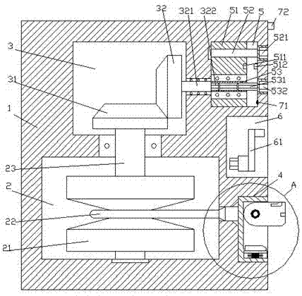
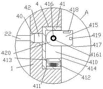
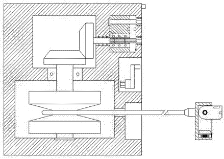
[0024] Such as Figure 1-Figure 7 As shown, a new energy vehicle charging device of the present invention includes a pile body 1, a storage cavity 2 is provided in the pile body 1, and a first cavity is provided in the pile body 1 above the storage cavity 2 Body 3, the pile body 1 on the right side of the first cavity 3 is provided with a second cavity body 5, and the pile body 1 on the right side of the receiving cavity 2 is provided with a mounting groove 4 in the outer wall, A storage groove 6 is provided in the outer side wall of the pile body 1 above the mounting groove 4, a communication hole 40 is provided between the mounting groove 4 and the receiving cavity 2, and the receiving cavity 2 is provided with A rotating shaft 23 extending up and down. The upwardly extending section of the rotating shaft 23 penetrates the inner wall of the pile 1 and is connected in rotation. The top end of the rotating shaft 23 extends into the first cavity 3 and is fixedly provided with T...


PUM


Abstract

The invention discloses new energy vehicle charging equipment. The equipment comprises a pile body. A receiving cavity is arranged in the pile body, a first cavity is arranged in the pile body, above the receiving cavity, a second cavity is arranged in the pile body, on the right of the first cavity, an installation and connection groove is arranged in the outer side wall of the pile body, on the right of the receiving cavity, a storage groove is arranged in the outer side wall of the pile body, above the installation and connection groove, a communication hole is arranged between the installation and connection groove and the receiving cavity, a rotating shaft which extends up and down is arranged in the receiving cavity, the upwards extending section of the rotating shaft penetrates the inner wall of the pile body and is rotatably connected with the inner wall of the pile body in a matching way, the extending tail end at the top of the rotating shaft extends into the first cavity and is fixedly provided with a first cone wheel, the top right of the first cone wheel is connected with a second cone wheel in a meshing way, a transmission shaft which extends to the right side is fixedly arranged on the right of the second cone wheel, the extending section at the right of the transmission shaft penetrates the wall body of the pile body and is rotatably connected with the wall body of the pile body in a matching way, and the extending tail end on the right of the transmission shaft is provided with a first external spline shaft which extends into the second cavity. The new energy vehicle charging equipment has the advantages of simple structure, convenience in operation, capability of lowering manufacturing cost and high security.

Description

Technical field [0001] The invention relates to the technical field of new energy vehicle charging, in particular to a new energy vehicle charging equipment. Background technique [0002] In recent years, the problem of urban environmental pollution has become more and more serious. Among them, automobile exhaust pollution is increasingly endangering people's health. With the increasing awareness of environmental protection, the rapid development of low-carbon economy and energy-saving emission reduction technologies, electric vehicles have The advantages of pollution have begun to be widely used in daily life. Charging piles are an important basic supporting charging facility for electric vehicles. The use process of charging piles is very similar to the process of car refueling. In the charging operation of electric vehicles, people need to remove the charging gun head from the charging pile and connect it to the charging port of the electric vehicle. After connecting and char...

Claims


Application Information

Patent Timeline
Patent Type & Authority Applications(China)
IPC IPC(8): B60L11/18H01R13/72
CPCB60L53/31H01R13/72Y02T10/70Y02T10/7072Y02T90/12Y02T90/16
Inventor 梁敏华
Owner FOSHAN CITY MOFAN AUTOMOTIVE SUPPLIES CO LTD
Why Eureka
Try Eureka