Pneumatic gear shifting control device and gear shifting control method of automated mechanical transmission

A technology of automatic transmission and pneumatic shifting, applied in the direction of transmission control, fluid pressure actuating device, mechanical equipment, etc., to achieve the effect of simple and reliable control, simple structure, and convenient installation and arrangement

Active Publication Date: 2017-11-21
HUBEI UNIV OF AUTOMOTIVE TECH
View PDF6 Cites 3 Cited by
  • Summary
  • Abstract
  • Description
  • Claims
  • Application Information

AI Technical Summary

Problems solved by technology

[0004] The object of the present invention is to provide a pneumatic shift control method and device for a mechanical automatic transmission in view of the above defects. This device directly controls the shift shaft to complete the corresponding shift action based on the rotary cylinder, and solves the problem of precise control of shift force and shift position. And other problems, and small size, simple structure

Method used


Image

  • Pneumatic gear shifting control device and gear shifting control method of automated mechanical transmission
  • Pneumatic gear shifting control device and gear shifting control method of automated mechanical transmission
  • Pneumatic gear shifting control device and gear shifting control method of automated mechanical transmission

Examples


Embodiment 1

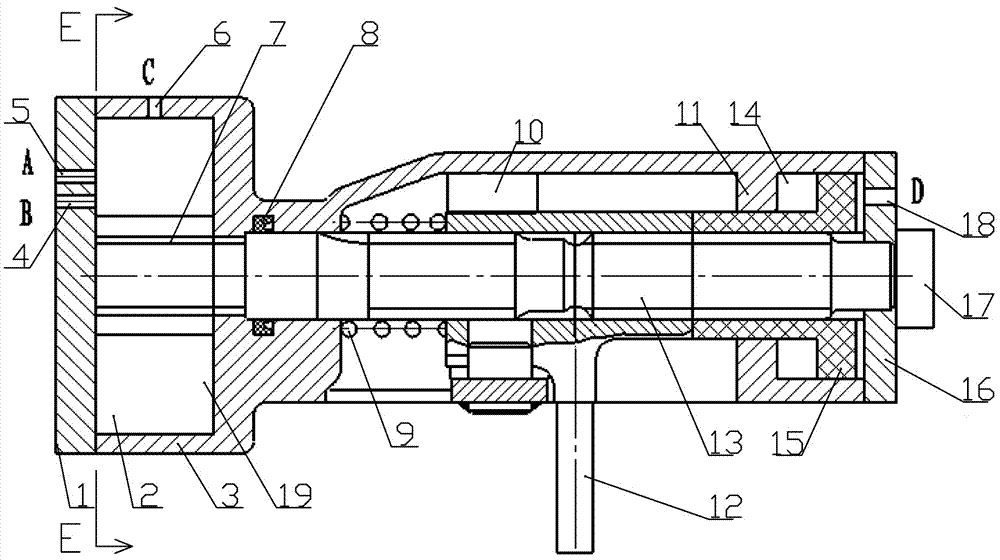
[0036] Such as Figure 1-5 As shown, a pneumatic shift control device for a mechanical automatic transmission includes a shift cylinder housing 3, a shift shaft 13 is installed inside the shift cylinder housing 3, and one end of the shift shaft 13 is provided with a useful The rotary gear shifting mechanism is used for gear shifting, and the other end is provided with a pneumatic gear selecting mechanism for gear selection; a shift dial 12 is installed on the shift shaft 13 .

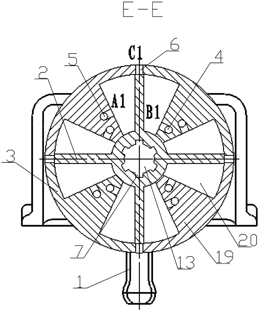
[0037] Further, the rotary shifting mechanism includes a rotor piston 2, which is sleeved on the end of the shift shaft 13 through a spline 7, and the rotor piston 2 is connected to a plurality of parts on the head of the shift cylinder housing 3. Cylinders 19 are matched, and the cylinders 19 are uniformly arranged on the head of the shift cylinder housing 3, and a plurality of sealed fan-shaped shift cavities 20 are formed between the plurality of cylinders 19. The outer end surface of the body 19 is...

Embodiment 2

[0050] The gear shift control method adopting any one of the pneumatic gear shift control device of the mechanical automatic transmission comprises the following steps:

[0051] Step1: When working, the cylinders of the four cylinder blocks 19 participate in the work at the same time, taking the No. 1 cylinder as an example;

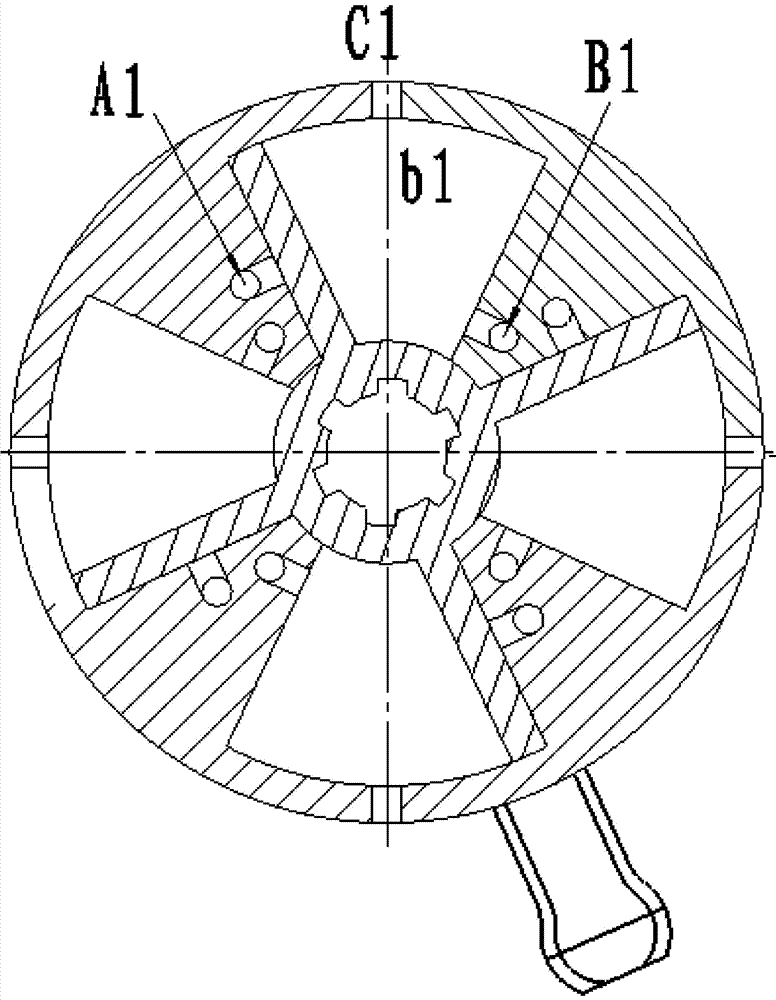
[0052] Step2: Shift from first gear to second gear. Initially, the shift knob 12 is in the first and third gear positions. At this time, the working chamber a1 of the fan-shaped shift chamber 20 is the smallest, and the working chamber b1 is the largest; the electromagnetic valve is controlled to make the A1 port intake, Port B1 is exhausted and port C1 is closed. At this time, the working chamber a1 of the No. 1 cylinder intakes air, and the working chamber b1 exhausts. Drive the shift shaft 13 to rotate, and the shift shaft 13 drives the shift dial 12 to rotate clockwise to the right to complete the action of shifting to the second gear. At this time, ...


PUM


Abstract

The invention discloses a pneumatic gear shifting control device and gear shifting control method of an automated mechanical transmission. The pneumatic gear shifting control device comprises a gear shifting cylinder shell, and a gear shifting shaft is mounted in the gear shifting cylinder shell; a rotating gear shifting mechanism used for gear shifting is arranged at one end of the gear shifting shaft; a pneumatic gear selecting mechanism used for gear selecting is arranged at the other end of the gear shifting shaft; and a gear shifting head is mounted on the gear shifting shaft. According to the pneumatic gear shifting control device, the gear shifting shaft is directly controlled to achieve corresponding gear shifting action based on a rotating cylinder, the problem about accurately controlling gear shifting force, gear shifting and neutral gear return positions is solved, the size is small, and the structure is simple.

Description

technical field [0001] The invention belongs to the technical field of transmission devices, and in particular relates to a pneumatic shift control device and a shift control method for a mechanical automatic transmission. Background technique [0002] With the development of automobile technology, automatic transmissions have been widely used in various vehicles. Mechanical automatic transmissions are widely used due to their simple structure, high transmission efficiency, and good reliability. [0003] In order to realize the automatic shifting of the mechanical transmission, a hydraulic scheme, an electric scheme or a pneumatic scheme can be used. At present, the mechanical automatic transmission that adopts the pneumatic shifting scheme ensures the torque required for shifting and realizes precise control of the shifting position through the linearly acting cylinder. In order to ensure the shifting torque, increase the diameter of the cylinder or increase the length of...

Claims


Application Information

Patent Timeline
Patent Type & Authority Applications(China)
IPC IPC(8): F16H61/4043F16H61/40F15B13/02
CPCF15B13/02F16H61/40F16H61/4043
Inventor 刘成武刘珂路姚胜华吕科
Owner HUBEI UNIV OF AUTOMOTIVE TECH
Why Eureka
Try Eureka