Unlock instant, AI-driven research and patent intelligence for your innovation.
Method and device for splicing panoramic image and portable terminal
What is Al technical title?
Al technical title is built by PatSnap Al team. It summarizes the technical point description of the patent document.
A panoramic image and image technology, applied in the field of image processing
Active Publication Date: 2017-11-21
SHENZHEN ARASHI VISION CO LTD
View PDF6 Cites 16 Cited by
Summary
Abstract
Description
Claims
Application Information
AI Technical Summary
This helps you quickly interpret patents by identifying the three key elements:
Problems solved by technology
Method used
Benefits of technology
Problems solved by technology
[0003] The purpose of the present invention is to provide a panoramic image splicing method, device and portable terminal, aiming at solving the problem that in the current panoramic images obtained by splicing multiple images, more obvious splicing traces will appear in the image splicing area
Method used
Image
Click on the blue label to locate the original text in one second.
Reading with bidirectional positioning of images and text.
Examples
Embodiment 1
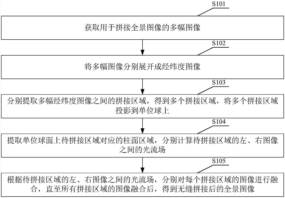
[0030] see figure 1 , the panoramic image stitching method provided by Embodiment 1 of the present invention includes the following steps:
[0031] S101. Acquire a plurality of images for splicing panoramic images.
[0032] S102. Expand the multiple images into latitude and longitude images respectively.
[0033] In Embodiment 1 of the present invention, S102 may specifically include the following steps:
[0034] Obtain a model that expands the captured image to a latitude-longitude image;
[0035] According to the model, the multiple images are respectively expanded to obtain multiple longitude and latitude images respectively corresponding to the multiple images.
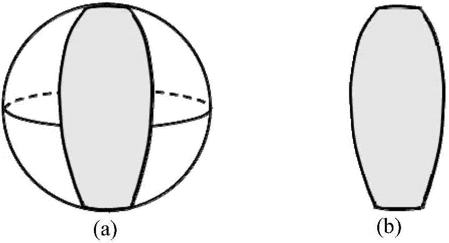
[0036] S103. Extract the spliced areas between the multiple latitude and longitude images respectively, obtain multiple spliced areas, and project the multiple spliced areas onto the unit sphere.
[0037] In Embodiment 1 of the present invention, S103 may specifically include the following steps:
[003...
Embodiment 2
[0056] see Figure 4 The panoramic image stitching device provided in Embodiment 2 of the present invention includes:
[0057] Obtaining module 11, is used for obtaining multiple images for splicing panoramic images;
[0058] Expanding module 12, is used for expanding multiple images into longitude and latitude images respectively;
[0059] The projection module 13 is used to extract the mosaic areas between multiple latitude and longitude images respectively, obtain a plurality of mosaic areas, and project the mosaic areas onto the unit sphere;
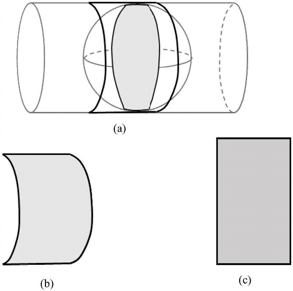
[0060] The optical flow field calculation module 14 is used to extract the cylindrical area corresponding to the area to be spliced on the unit sphere, and calculate the optical flow field between the left and right images of the area to be spliced respectively;
[0061] The fusion module 15 is used to fuse the images of each spliced area according to the optical flow field between the left and right images of the area to be ...
Embodiment 3
[0067] Embodiment 3 of the present invention also provides a computer-readable storage medium, the computer-readable storage medium stores a computer program, and when the computer program is executed by a processor, the panorama image stitching method provided in Embodiment 1 of the present invention is implemented. A step of.
PUM
Abstract
The invention is suitable for the field of image processing, and provides a method and device for splicing a panoramic image and a portable terminal. The method includes obtaining a plurality of images used for splicing the panoramic image; unfolding the plurality of images into longitude and latitude images; extracting splicing areas among the plurality of longitude and latitude images to obtain a plurality of splicing areas, and projecting the plurality of splicing areas to a unit ball; extracting a cylindrical surface area corresponding to an area to be spliced on a unit ball surface, and calculating an optical flow field between left and right images of the area to be spliced; and fusing images of the splicing areas according to the optical flow field between the left and right images of the area to be spliced till the images of all the splicing areas are fused, thereby obtaining a panoramic image after seamless splicing. The method for splicing the panoramic image can realize smooth transition between fusion areas, thereby achieving an effect of seamless splicing.
Description
technical field [0001] The invention belongs to the field of image processing, and in particular relates to a panoramic image mosaic method, device and portable terminal. Background technique [0002] Compared with flat images, panoramic images can record 360° images around the shooting location, thereby bringing people a strong sense of reality and three-dimensionality. Therefore, there are broad application prospects in many industries such as film and television, tourism, and real estate. At present, most panoramic images are obtained by splicing multiple images, and more obvious splicing traces will appear in the image splicing area, which seriously affects the quality of the final panoramic image and the visual effect it brings to people. Contents of the invention [0003] The purpose of the present invention is to provide a panoramic image stitching method, device and portable terminal, aiming to solve the problem that there are obvious stitching traces in the image...
Claims
Application Information
Patent Timeline
Application Date:The date an application was filed.
Publication Date:The date a patent or application was officially published.
First Publication Date:The earliest publication date of a patent with the same application number.
Issue Date:Publication date of the patent grant document.
PCT Entry Date:The Entry date of PCT National Phase.
Estimated Expiry Date:The statutory expiry date of a patent right according to the Patent Law, and it is the longest term of protection that the patent right can achieve without the termination of the patent right due to other reasons(Term extension factor has been taken into account ).
Invalid Date:Actual expiry date is based on effective date or publication date of legal transaction data of invalid patent.
