
A direction adjusting device for laying cables

A direction adjustment and cable technology, applied in the direction of cable laying equipment, etc., can solve the problems of dead knots, failure of carrying, and tangled cables, so as to improve work efficiency, ensure work efficiency, and reduce manufacturing costs.

Active Publication Date: 2019-07-02
许昌合达智能电气有限公司
View PDF9 Cites 0 Cited by
  • Summary
  • Abstract
  • Description
  • Claims
  • Application Information

AI Technical Summary

Problems solved by technology

Although the cost of the former is not high, it is easy to make the height of the top machine room of the existing tower crane insufficient, which increases the difficulty of design; although the latter will not affect the height of the machine room, it will increase the cost of purchasing the steering machine
In addition, once the machinery fails, it is very easy to cause the cables to be entangled or knotted, resulting in the failure of the delivery and even the failure of the mechanical equipment.
[0003] In view of the above problems, the present invention provides a simple and quick inspection of the cable quality and whether it is broken before laying, without the need to take out the entire cable before laying the cable for inspection, and after the inspection before laying the cable, arrange it before laying the cable. Calibrating cables is time-consuming and labor-intensive

Method used


Image

  • A direction adjusting device for laying cables
  • A direction adjusting device for laying cables
  • A direction adjusting device for laying cables

Examples


Embodiment 3

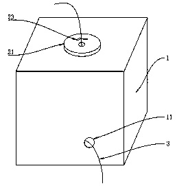
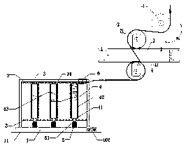
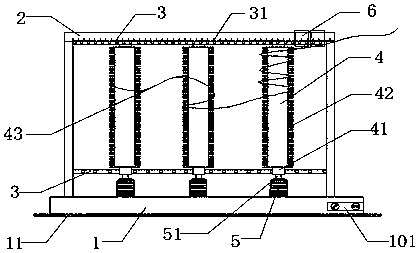
[0032] Example 3 see Figures 1 to 5 , on the basis of Embodiment 1, Embodiment 2 and Embodiment 3, the following is a detailed description of the tensioning direction wheel in a direction adjustment device for laying cables of the present invention, specifically a direction adjustment for laying cables The device includes a box body 1, and at least one volume control wheel is installed in the box body 1. In this embodiment, a carding volume control wheel consisting of three volume control wheels is preferred. Specifically, the combing control wheel includes a chassis 1, a support body 2, a control wheel 4, a slideway 3, and a working motor 5. The support body is a square frame structure, and is arranged on the top of the chassis 1, and the top of the support body 2 The cable-winding detection head 6 is socketed, the slideway 3 is arranged on the upper and lower symmetrical positions of the support body 2, and several control wheels 4 are arranged in the vertical direction bet...


PUM


Abstract

The invention relates to the field of cable equipment, particularly to a direction adjusting device for laying of a cable. The device is characterized in that the device includes a box body, one side face of the box body is provided with a hole for entering of a cable, a teasing quantity-controlling wheel is arranged behind the hole for entering of the cable, a tensioning direction wheel is arranged behind the teasing quantity-controlling wheel, a cable outgoing head of the teasing quantity-controlling wheel parallelly penetrates through a cable inlet of the direction adjusting device, the top of the box body is provided with a rotary wheel, the upper end of the rotary wheel is in running fit with a rotary wheel hole, the lower end of the rotary wheel is fixed on the lower bottom surface of the outer surface of the box body, the cable enters from the hole for entering of the cable into the teasing quantity-controlling wheel and the tensioning direction wheel in sequence and is then led out from the rotary wheel hole. The direction adjusting device for laying of the cable has the following beneficial effects that the direction of laying of the cable can be rapidly adjusted, during laying of the cable, the taking-up and paying-off quantities of the cable can be freely controlled, thereby preventing twining and winding, the problem of angle rail sleeving and winding during laying of a cable can be well solved, and the device is convenient to mount.

Description

technical field [0001] The invention relates to the field of cable equipment, in particular to a direction adjusting device for laying cables. Background technique [0002] For power and telecommunication equipment, the pre-laying calibration cable is generally used to connect the pre-laying calibration equipment with the pre-laying calibration equipment. The pre-laying calibration cable plays a role in conduction. The role of the verification signal. However, the calibration cable before laying the cable is often long, and the entire calibration cable needs to be taken out before the calibration before laying the cable. And slender calibration cables before laying cables tend to be entangled together, which brings inconvenience to the calibration cables before laying cables, and at the same time, may also damage the calibration cables before laying cables in the finishing process. With the continuous development of society, the use of cables is becoming more and more popu...

Claims


Application Information

Patent Timeline
Patent Type & Authority Patents(China)
IPC IPC(8): H02G1/06
CPCH02G1/06
Inventor 王俊霞
Owner 许昌合达智能电气有限公司
Learn More