Circulating peeling and cleaning mechanism

A cleaning mechanism and circulating technology, applied in the field of machinery, can solve the problems of high cost, low efficiency and large workload.

Inactive Publication Date: 2017-11-24
WUXI NANLIGONG TECH DEV
View PDF8 Cites 0 Cited by
  • Summary
  • Abstract
  • Description
  • Claims
  • Application Information

AI Technical Summary

Problems solved by technology

[0002] At present, the production and processing of agricultural products such as peach pits are manually peeled,

Method used


Image

  • Circulating peeling and cleaning mechanism
  • Circulating peeling and cleaning mechanism
  • Circulating peeling and cleaning mechanism

Examples


Embodiment Construction

[0020] In order to better understand the improvement made by the present invention compared with the prior art, the specific embodiments of the present invention will be described in detail below.

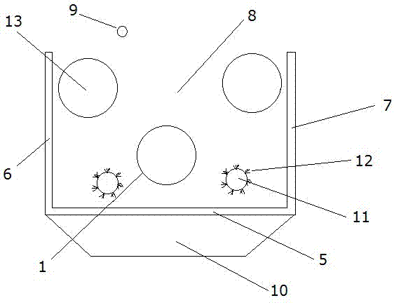
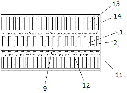
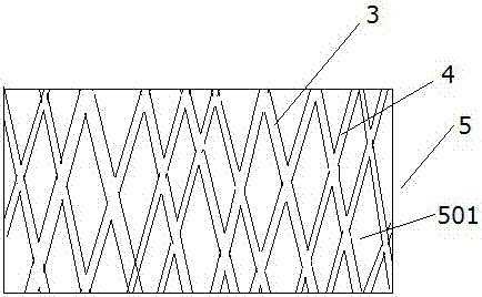
[0021] Such as figure 1 As shown, the circulation type peeling and cleaning mechanism includes a driving shaft 1, and on the driving shaft 1, a groove 2 is spirally wound from left to right, and the depth D of the groove 2 is 0.3~0.5cm, corresponding to The distance L between the adjacent grooves 2 is 1~1.5cm; it also includes a sawtooth bar 15, which is embedded in the groove 2, from Figure 4 It can be clearly seen that the sawtooth bar 15 includes a base 1501 and sawtooth 1502. When embedded, the base 1501 is inserted into the groove 2, and the sawtooth 1502 is exposed outside, and the sawtooth bar 15 moves along the groove 2 from spirally wound on the surface of the driving shaft 1 from left to right, such as figure 2 As shown, the surface of the driving shaft 1 is spirally ...


PUM

PropertyMeasurementUnit
Depthaaaaaaaaaa
Heightaaaaaaaaaa

Abstract

The invention discloses a circulating peeling and cleaning mechanism. The circulating peeling and cleaning mechanism comprises a driving shaft, grooves are formed in the driving shaft in a helically wound manner from left to right, the depth D of the grooves is 0.3-0.5cm, and the distance L between every two adjacent grooves is 1-1.5cm. The mechanism further comprises sawtooth strips embedded in the grooves, and the sawtooth strips are wound on the surface of the driving shaft spirally from left to right along the grooves. A bottom plate formed by cross connection of a plurality of warp strips and a plurality of weft strips is arranged under the driving shaft, and the height H between the bottom plate and the driving shaft is 5-10cm. A first side plate and a second side plate are arranged on two sides of the driving shaft respectively, the first side plate, the second side plate and the bottom plate form an accommodating space, and the driving shaft is located in the accommodating space. A spray device is arranged over the accommodating space. With the circulating peeling and cleaning mechanism, to-be-processed articles are subjected to circular processing, and thorough peeling is guaranteed.

Description

technical field [0001] The invention belongs to the technical field of machinery, and in particular relates to a circular peeling and cleaning mechanism. Background technique [0002] At present, the production and processing of agricultural products such as peach pits are manually peeled, and the peach pits must be cleaned. This manual processing method is inefficient, heavy in workload, and high in cost. Contents of the invention [0003] The technical problem to be solved by the present invention is to provide a circular peeling and cleaning mechanism with novel structure, high peeling efficiency and convenient cleaning. [0004] In order to solve the above-mentioned technical problems, the technical solution adopted by the present invention is that the circulation type peeling and cleaning mechanism includes a driving shaft, and on the driving shaft, there is a groove spirally wound from left to right, and the groove of the groove is The depth D is 0.3~0.5cm, and the ...

Claims


Application Information

Patent Timeline
IPC IPC(8): A23N12/02A23N5/00
Inventor 何非张荣生
Owner WUXI NANLIGONG TECH DEV
Why Eureka
Try Eureka