Induction-type fruit peeling machine

A peeling machine and inductive technology, applied in the peeling of vegetables or fruits, fruit core removal devices, applications, etc., can solve the problem of no way to control the peeling thickness, low quality and low stability of peeling and other problems, to achieve the effect of improving the practicality and peeling quality, and improving the peeling efficiency

Inactive Publication Date: 2018-03-02
陈建霖
View PDF0 Cites 10 Cited by
  • Summary
  • Abstract
  • Description
  • Claims
  • Application Information

AI Technical Summary

Problems solved by technology

[0003] Yet existing fruit peeling machine has some deficiencies in use, and the supporting plate that fixes fruit is used is less stable when fixing fruit, and the thickness degree of peeling has no way to control well, the peeled lower quality

Method used


Image

  • Induction-type fruit peeling machine

Examples


Embodiment 1

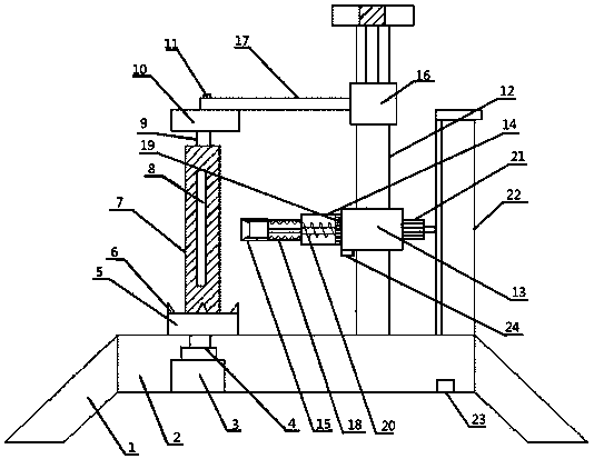
[0018] An inductive fruit peeling machine, comprising a leg 1, a base 2, a motor 3, a telescopic rod 4, a supporting plate 5, a shelling tube 7, a connecting rod 9, a turntable 10, a rotating shaft 11, a peeling knife 15 and a support rod 12;

[0019] The damping legs 1 are welded on both sides of the base 2, and the base 2 is provided with a motor 3; The motor 3 is connected by transmission; the center of the surface on the supporting plate 5 is welded with a nuclear tube 7; 7 is provided with a U-shaped hole 8; the top of the denuclearization tube 7 is threadedly connected with a connecting rod 9, and the connecting rod 9 is fixedly connected with the turntable 10 through the rotating shaft 11; the base 2 is located on one side of the supporting plate 5 A pillar is welded; the support rod 12 is provided with a sleeve 16; the sleeve 16 is connected to the turntable 10 through a connecting cross bar 17;

[0020] Described pole 12 is provided with movable casing 13, and movab...

Embodiment 2

[0022] An inductive fruit peeling machine, comprising a leg 1, a base 2, a motor 3, a telescopic rod 4, a supporting plate 5, a shelling tube 7, a connecting rod 9, a turntable 10, a rotating shaft 11, a peeling knife 15 and a support rod 12;

[0023] The damping legs 1 are welded on both sides of the base 2, and the base 2 is provided with a motor 3; The motor 3 is connected by transmission; the center of the surface on the supporting plate 5 is welded with a nuclear tube 7; 7 is provided with a U-shaped hole 8; the top of the denuclearization tube 7 is threadedly connected with a connecting rod 9, and the connecting rod 9 is fixedly connected with the turntable 10 through the rotating shaft 11; the base 2 is located on one side of the supporting plate 5 A pillar is welded; the support rod 12 is provided with a sleeve 16; the sleeve 16 is connected to the turntable 10 through a connecting cross bar 17;

[0024] Described pole 12 is provided with movable casing 13, and movab...


PUM


Abstract

The invention discloses an induction type fruit peeling machine, which comprises legs, a base, a motor, a telescopic rod, a supporting plate, a shelling tube, a connecting rod, a turntable, a rotating shaft, a peeling knife and a support rod, and the two sides of the base are The shock-absorbing outriggers are welded, the base is equipped with a motor, and the surface of the base is provided with a support plate. The center of the bottom of the support plate is connected to the motor transmission inside the base through a telescopic rod. The limited teeth are welded on the board around the nuclear removal tube, the top of the nuclear removal tube is threadedly connected with a connecting rod, and the connecting rod is fixedly connected with the turntable through the rotating shaft, and a pillar is welded on the side of the supporting plate on the base, and the supporting rod is provided with The casing, the casing and the turntable are connected by connecting cross bars, the support rod is provided with a movable casing, the movable casing is provided with a fixed pipe, the fixed pipe is provided with a propulsion motor, and the peeling knife is arranged on the movable pipe. The invention not only can better fix the fruit, but also allows the blade to cling to the surface of the fruit, thereby improving the practicability and peeling quality.

Description

technical field [0001] The invention relates to the technical field of peeling machines, in particular to an induction type fruit peeling machine. Background technique [0002] Fruit refers to the edible plant fruit that is juicy and the main taste is sweet and sour. It not only contains rich nutrition, but also can help digestion. Some fruits need to be peeled when eating. Fruit peeling machine refers to machine Imitate the peeling action of human hands to remove the peel of the fruit, which is convenient for subsequent processing and consumption, and improves the quality. [0003] Yet existing fruit peeling machine has some deficiencies in use, and the supporting plate that fixes fruit is used is less stable when fixing fruit, and the thickness degree of peeling has no way to control well, the peeled lower quality. Contents of the invention [0004] The invention aims at the deficiencies of the prior art, and provides an induction type fruit peeler with stable peeling ...

Claims


Application Information

Patent Timeline
Patent Type & Authority Applications(China)
IPC IPC(8): A23N7/02A23N4/12A23N4/02
CPCA23N7/026A23N4/02A23N4/12
Inventor 陈建霖
Owner 陈建霖
Why Eureka
Try Eureka