Shoe cabinet

A shoe cabinet and cabinet body technology, applied in the field of shoe cabinets, can solve the problems of wasting space in shoe cabinets and cannot use one item for multiple purposes, and achieve the effects of diverse functions, space saving and convenient use.

Inactive Publication Date: 2017-11-24
钟光远
View PDF0 Cites 4 Cited by
  • Summary
  • Abstract
  • Description
  • Claims
  • Application Information

AI Technical Summary

Problems solved by technology

[0002] Shoe cabinets can help people store all kinds of shoes neatly, but the existing shoe cabinets generally have a waste of space and cannot be used for multiple purposes.

Method used


Image

  • Shoe cabinet

Examples


Embodiment 1

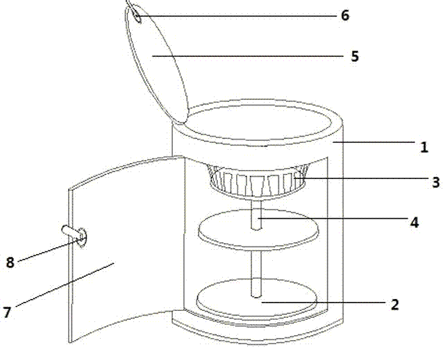
[0016] A shoe cabinet, including a cabinet body 1 and a shoe rack, the shoe rack is located in the cabinet body 1, the shoe rack includes several storage platforms 2, a central rotating shaft 4 and several shoe supports 3, and the several storage platforms 2 are arranged from top to bottom Arranged in parallel, and rotatably connected with the central rotating shaft 4, several shoe-stays 3 are arranged on the peripheral edge of the storage platform.

[0017] The cabinet body 1 is cylindrical. The cabinet body 1 is provided with two doors, the No. 1 door 5 is located at the top of the cabinet body 1 , and the No. 2 door is located at the front of the cabinet body 1 .

[0018] Doors 1 and 2 have handles.

[0019] When in use, the user can open the two doors as needed to take the shoes.


PUM


Abstract

The invention provides a shoe cabinet, which includes a cabinet body (1) and a shoe rack, the shoe rack is located in the cabinet body (1), and is characterized in that the shoe rack includes several storage tables (2), a central A rotating shaft (4) and several shoe supports (3), the shoe rack is arranged inside the cabinet (1), and the several storage tables (2) are arranged in parallel from top to bottom, and are aligned with the central rotating shaft (4) Rotationally connected, the plurality of shoe-stays (3) are arranged on the peripheral edge of the storage platform. The invention has the beneficial effects of saving space, one thing with multiple functions, and preventing shoes from falling dust.

Description

technical field [0001] The invention relates to the field of furniture, in particular to a shoe cabinet. Background technique [0002] Shoe cabinets can help people store all kinds of shoes neatly, but the existing shoe cabinets generally have a waste of space and cannot be used for multiple purposes. Contents of the invention [0003] The present invention provides a shoe cabinet to overcome at least one defect described in the above prior art. [0004] A shoe cabinet, comprising a cabinet body and a shoe rack, the shoe rack is located in the cabinet, characterized in that the shoe rack includes several storage platforms, a central rotating shaft and several shoe stands, and the several storage platforms are The upper part and the lower part are arranged in parallel, and are rotatably connected with the central rotating shaft, and the plurality of shoe stays are arranged on the peripheral edge of the storage platform. [0005] Further, the cabinet body is cylindrical. ...

Claims


Application Information

Patent Timeline
IPC IPC(8): A47B61/04A47B49/00
CPCA47B61/04A47B49/004
Inventor 钟光远
Owner 钟光远
Why Eureka
Try Eureka