
A high and low channel sampling rate distribution method for EEG signal acquisition

A method of distribution, EEG signal technology, applied in the direction of diagnostic signal processing, electrical digital data processing, medical science, etc., to achieve the effect of equal sampling intervals

Active Publication Date: 2020-12-22
SOUTH CHINA UNIV OF TECH
View PDF7 Cites 0 Cited by
  • Summary
  • Abstract
  • Description
  • Claims
  • Application Information

AI Technical Summary

Problems solved by technology

[0003] In order to solve the shortcomings and shortcomings of a single continuous cycle switching sampling method, the present invention provides a method for distributing the sampling rate of channels for EEG signal acquisition, which uses a regular sorting method to switch channels, and realizes using within a sampling cycle. A small number of channels are assigned more samples than the rest

Method used


Image

  • A high and low channel sampling rate distribution method for EEG signal acquisition
  • A high and low channel sampling rate distribution method for EEG signal acquisition
  • A high and low channel sampling rate distribution method for EEG signal acquisition

Examples


example 1

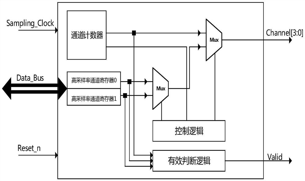
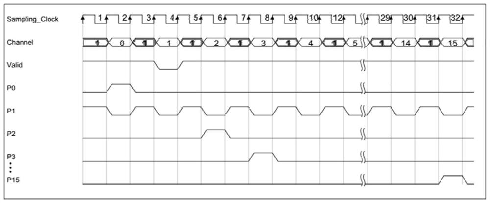
[0026]In this example, only channel 1 is allocated as a high sampling rate channel, and both high sampling rate channel registers are written with 1. Timing diagram such asfigure 2 Shown. In the figure, the Sampling_Clock labeled 1, 3, 5,..., 31 is the odd sampling clock, which corresponds to the shaded part of the Channel, and the Sampling_Clock labeled 2, 4, 6, ..., 32 in the figure is the even sampling clock. Corresponds to the non-shaded part of the Channel. At the odd-numbered sampling clocks labeled 1, 5, 9,..., 29, read the high sampling rate channel register 0 and output the value 1 to Channel, and at the odd-numbered sampling clocks labeled 3, 7, 11,..., 31 Sampling clock, read high sampling rate channel register 1 and output the value 1 to Channel. At the even-numbered sampling clock, the channel counter is incremented by 1, and if it reaches the maximum value (15 in this example), the counting is restarted, and the value of the channel counter is output to the Channel. In...

example 2

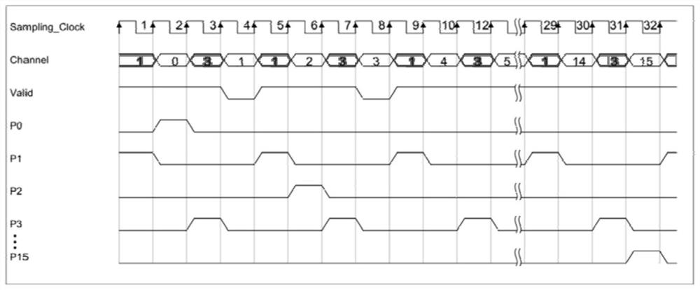
[0028]In this example, channel 1 and channel 3 are allocated as high-sampling-rate channels, high-sampling-rate channel register 0 is written with 1, and high-sampling-rate channel register 1 is written with 3. Timing diagram such asimage 3Shown. At the odd-numbered sampling clocks labeled 1, 5, 9,..., 29, read the high sampling rate channel register 0 and output the value 1 to Channel, and at the odd-numbered sampling clocks labeled 3, 7, 11,..., 31 Sampling clock, read high sampling rate channel register 1 and output value 3 to Channel. At the even-numbered sampling clock, the channel counter is incremented by 1, and if it reaches the maximum value (15 in this example), the counting is restarted, and the value of the channel counter is output to the Channel. In the even-numbered sampling clock labeled 4, the output channel counter is 1 at this time, and the valid judgment logic circuit judges that the value has been stored in the high sampling rate channel register group, and the ...


PUM


Abstract

The invention discloses a channel sampling rate distribution method for electroencephalogram collection. According to the method, a sampling clock period is divided into an odd-order sampling clock period and an even-order sampling clock period. A small quantity of channels with high sampling rates are determined and alternately distributed in the odd-order sampling clock period, and a great quantity of other channels are alternately distributed in the even-order sampling clock period. According to the channel sampling rate distribution method for the electroencephalogram collection, more sampling points can be distributed to a small part of sampling channels. Meanwhile, by introducing effective signals, the channels repeatedly distributed in the even-order sampling clock period (already distributed in the odd-order sampling clock period) can be indicated, and therefore equal sampling interval of each sampling channel can be ensured.

Description

Technical field[0001]The invention relates to the field of bioelectric signal acquisition and integrated circuits, in particular to a method for allocating high and low channel sampling rates of brain electric signal acquisition.Background technique[0002]EEG signal acquisition is a method of using electronic technology to extract brain nerve electrical signals. It plays an important role in studying pathology, disease diagnosis, and surgical positioning. The EEG signal acquisition is developing towards more and more acquisition channels. At the same time, the volume, power consumption and data bandwidth requirements of the EEG signal acquisition system are getting higher and higher. The current EEG signal acquisition method basically uses the method of continuous cyclic switching of multiple switches, and each channel has the same sampling rate. For EEG signals, in general, only some channels (such as epileptic seizures) require a higher sampling rate than usual (that is, the high s...

Claims


Application Information

Patent Timeline
Patent Type & Authority Patents(China)
IPC IPC(8): A61B5/0476G06F13/16G06F13/40
CPCA61B5/72A61B5/369G06F13/1668G06F13/4022
Inventor 吴朝晖韦胜昌李斌
Owner SOUTH CHINA UNIV OF TECH
Learn More