Upper tool mounting structure for fin transecting die

An installation structure and cross-cutting technology, which is applied in the field of fin molds, can solve problems such as looseness, cross-cutting quality, and affecting the gap between knife edges, etc., and achieve the effects of prolonging service life, ensuring cross-cutting quality, and simple structure

Pending Publication Date: 2017-11-24
WUXI HI TECH PRECISION MOLD
View PDF6 Cites 1 Cited by
  • Summary
  • Abstract
  • Description
  • Claims
  • Application Information

AI Technical Summary

Problems solved by technology

[0003] The purpose of the present invention is to address the above problems, to provide a mounting structure for the upper knife of the fin cross-cutting die, to solve the problem that the upper knife of the existing fin cross-cutting die is installed on the sliding plate, and after a period of use, no oil lubricating block There will be a gap between the sliding plate and the looseness, which will affect the gap between the knife edge and the problem of cross-cutting quality.

Method used


Image

  • Upper tool mounting structure for fin transecting die
  • Upper tool mounting structure for fin transecting die
  • Upper tool mounting structure for fin transecting die

Examples


Embodiment Construction

[0013] The technical solutions of the present invention will be further described below in conjunction with the accompanying drawings and through specific implementation methods. It should be understood that the embodiments described here are only used to explain the present invention, but not to limit the present invention.

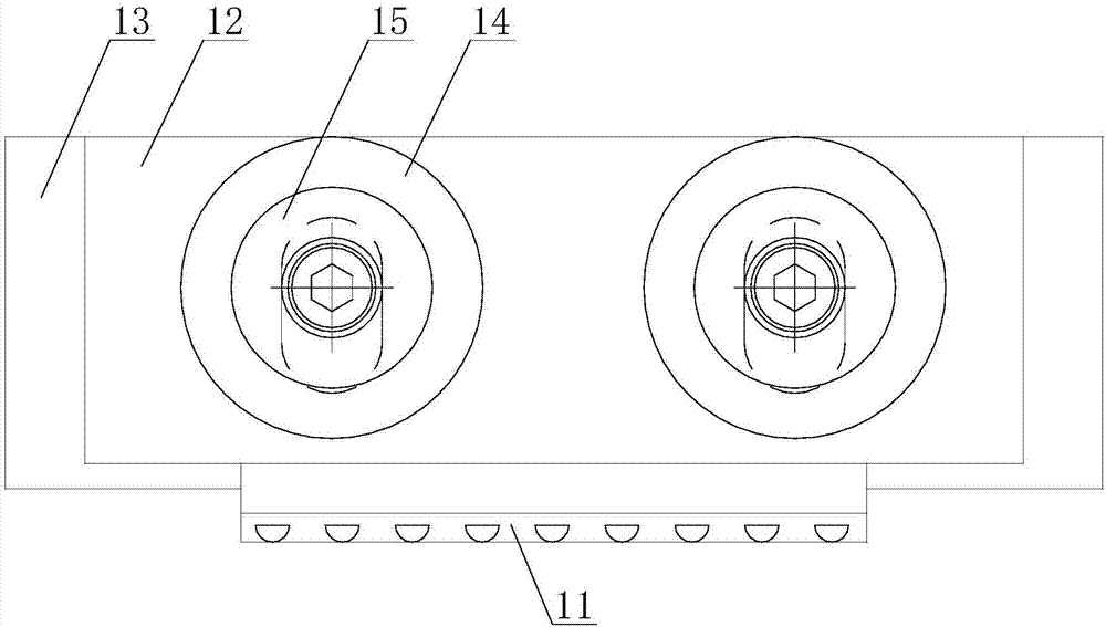
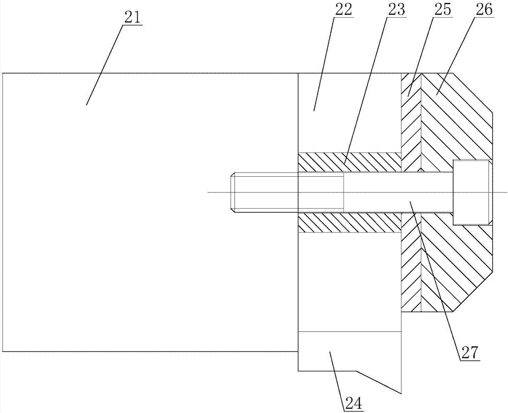
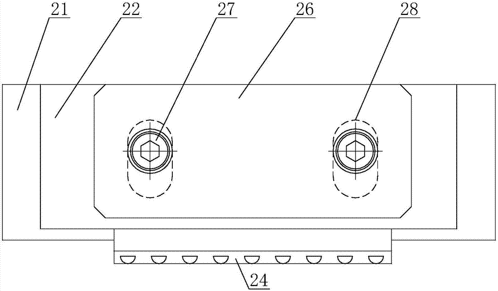
[0014] Please refer to figure 2 and image 3 As shown, in this embodiment, an upper knife installation structure of a fin cross-cutting die includes an upper knife seat 21, the right end of the upper knife seat 21 is provided with a sliding plate 22 and a limit post 23, and the sliding The plate 22 is a square structure, and the sliding plate 22 can move up and down and is arranged on the upper knife seat 21. The lower end of the sliding plate 22 is connected with the upper knife 24, and the sliding plate 22 has an elongated hole 28. The length direction of the strip hole 28 is parallel to the vertical direction, the left end of the spacer post 23 is ...


PUM


Abstract

The invention discloses an upper tool mounting structure for a fin transecting die; the upper tool mounting structure comprises an upper tool holder; one end of the upper tool holder is provided with a sliding plate and a limiting post, the sliding plate is vertically movably disposed on the upper tool holder, an upper tool is connected to the lower end of the sliding plate, the sliding plate is provided with an elongated hole, one end of the limiting post is abutted to the upper tool holder, the other end of the limiting post is passed through the elongated hole and is provided with a non-lubricating slider, one side of the non-lubricating slider is attached to the sliding plate, the other side of the non-lubricating slider is provided with a first fitting end face and is provided with a cover plate, the area of a part of the cover plate fitting the first fitting end face is not less than 80% of that of the first fitting end face, and the cover plate is fixedly connected with the upper tool holder. The area of the part of the cover plate fitting the first fitting end face of the non-lubricating slider is not less than 80% of that of the first fitting end face, tight fit between the non-lubricating slider and the sliding plate is effectively guaranteed, loosening is avoided occurring just after using for a period of time, and transecting quality is guaranteed accordingly.

Description

technical field [0001] The invention relates to a fin die, in particular to an upper knife installation structure of a fin cross-cut die. Background technique [0002] With the increasingly fierce competition in the air conditioner market and the ever-changing products, people have higher and higher requirements for the quality and performance of air conditioners. The air-conditioning fin die is a die used to produce air-conditioning fins, which is a high-precision cold stamping progressive die. The fin cross-cutting die is an important part of the air-conditioning fin die. It is the last process of the air-conditioning fin die. Its function is to cut the fins transversely. The fin cross-cutting die on the existing market, its upper knife 11 is installed on the sliding plate 12 of square structure, as figure 1 As shown, the sliding plate 12 is driven by the cylinder to slide up and down, and the sliding plate 12 is located between the upper knife seat 11 and the oil-free l...

Claims


Application Information

Patent Timeline
Patent Type & Authority Applications(China)
IPC IPC(8): B21D28/14
CPCB21D28/14
Inventor 蒋智远施展
Owner WUXI HI TECH PRECISION MOLD
Why Eureka
Try Eureka