Brightness correction system and method

A brightness correction and brightness technology, which is applied in cathode ray tube indicators, instruments, static indicators, etc., can solve the problems of unsuitable display screens and poor brightness detection accuracy, and achieve low cost, improved accuracy, and improved repair accuracy Effect

Active Publication Date: 2019-11-08
WUHAN JINGLI ELECTRONICS TECH +1
View PDF8 Cites 1 Cited by
  • Summary
  • Abstract
  • Description
  • Claims
  • Application Information

AI Technical Summary

Problems solved by technology

[0007] Aiming at at least one defect or improvement requirement of the prior art, the present invention provides a brightness correction system and method, the purpose of which is to solve the inability of the methods for eliminating the influence of the viewing angle in the prior art to be applicable to various The display screen with luminous characteristics leads to the problem of poor accuracy of brightness detection

Method used


Image

  • Brightness correction system and method
  • Brightness correction system and method

Examples


Embodiment Construction

[0037] In order to make the object, technical solution and advantages of the present invention clearer, the present invention will be further described in detail below in conjunction with the accompanying drawings and embodiments. It should be understood that the specific embodiments described here are only used to explain the present invention, not to limit the present invention. In addition, the technical features involved in the various embodiments of the present invention described below can be combined with each other as long as they do not constitute a conflict with each other.

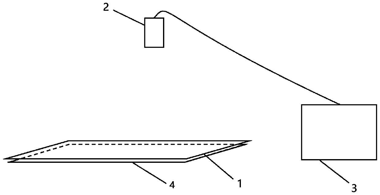
[0038] figure 1 It is a schematic diagram of the composition and structure of the brightness correction system provided by the embodiment of the present invention; figure 1 Said, the brightness correction system includes a scattering film layer 1, a CCD camera 2 and an image processing terminal 3; wherein,

[0039] The scattering film layer 1 is placed between the display screen 4 to be tested...


PUM


Abstract

The invention discloses a brightness correction system and a brightness correction method, and relates to the technical field of display. The system comprises a scattering film layer, an image acquisition unit and a brightness calculation unit. The scattering film layer is placed between a to-be-tested display screen and an image acquisition device. The size of the scattering film layer is not smaller than that of the to-be-tested display screen. The scattering film layer is used for dispersing light with a single emitting direction emitted by the to-be-tested display screen into a plurality of emitting directions. The image acquisition device is used for shooting a display screen image containing a scattering film layer. The brightness calculation unit is used for extracting an area wherethe display screen is located from the display screen image and calculating a brightness value of each pixel point in the area where the display screen is located. Starting from the light-emitting angle of the display screen, the light which is emitted by the display screen and has a single emitting direction is dispersed into a plurality of emitting angles through the scattering film layer. Therefore, the quantity of the light entering the view field of the camera is increased as much as possible. The influence of the view field angle is reduced. The accuracy of subsequent brightness measurement and color spot repair is improved.

Description

technical field [0001] The invention belongs to the field of display technology, and more specifically relates to a brightness correction system and method. Background technique [0002] In the production process of flat-panel displays, there will inevitably be color spot defects (Mura), which will lead to uneven brightness of the display panel and affect the image quality; Demura equipment is an integrated high-precision professional signal generator, standard optical measuring instrument, automatic pressing It is a color spot defect repair system that integrates connection and control adjustment software. In the brightness correction system, the first link is to take pictures of the display screen with a CCD camera and detect the brightness. Whether the brightness of the display screen can be accurately photographed and detected is very important for the final repair effect. Because the display screen has the light-emitting characteristic of side-view light leakage, the d...

Claims


Application Information

Patent Timeline
Patent Type & Authority Applications(China)
IPC IPC(8): G09G5/10
CPCG09G5/10G09G2320/0626
Inventor 冯晓帆郑增强刘璐宁轩慎振
Owner WUHAN JINGLI ELECTRONICS TECH
Why Eureka
Try Eureka