Supercharge Your Innovation With Domain-Expert AI Agents!

Punching forming mold

A technology of forming molds and punching holes is applied in the field of lamp production molds, which can solve the problems of increasing the number of workers and fixing the structure, and achieve the effect of strong versatility

Pending Publication Date: 2017-11-24
苏州申达洁净照明股份有限公司
View PDF9 Cites 0 Cited by
  • Summary
  • Abstract
  • Description
  • Claims
  • Application Information

AI Technical Summary

Problems solved by technology

However, the existing forming abrasives usually have a fixed structure, so they can only be stamped for one product. If you need to stamp other products with different needs, you need to replace different molds
Moreover, sometimes a lamp base plate needs to be punched separately by multiple different equipment, and the number of workers required will increase accordingly.

Method used


Image

  • Punching forming mold
  • Punching forming mold
  • Punching forming mold

Examples


Embodiment Construction

[0016] The present invention will be further described below in conjunction with the accompanying drawings.

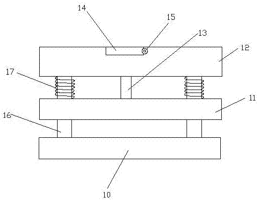
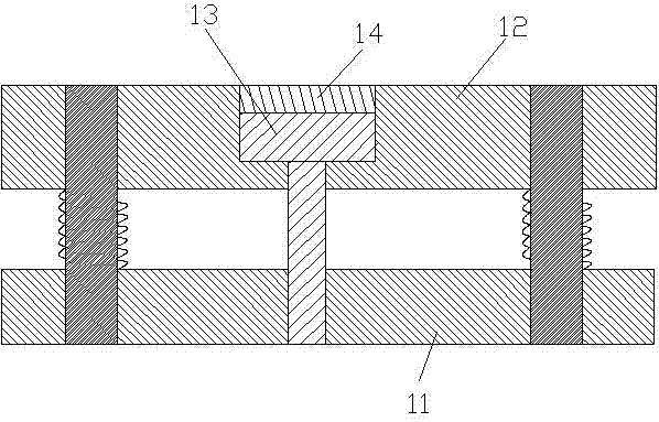
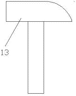
[0017] Such as Figure 1-Figure 4 As shown, a punching forming mold includes a lower template 10 and a stripping plate 11 and a splint 12 arranged above the lower template 10, and a punch placement groove with a T-shaped cross section is arranged in the splint 12, The punch placement groove is provided with a punch 13 whose lower end can pass through the stripper plate 11, and the punch 13 can move up and down relative to the punch placement groove, and the side of the splint 12 is also provided with There is a slotted knife slot communicating with the upper end of the punch placement slot, the slotted knife slot is provided with a slotted knife 14 for locking the punch 13, and the lower template 10 is provided with a 13 corresponding punching holes.

[0018] By inserting the corresponding inserting knife in the punch placement slot, it is ensured that the punch is f...


PUM


Abstract

The invention discloses a punching forming mold. The punching forming mold comprises a lower mold plate, a stripper plate and a clamping plate, wherein the stripper plate and the clamping plate are arranged above the lower mold plate. A puncher pin storage groove with the T-shaped section is formed in the clamping plate. A puncher pin is arranged in the puncher pin storage groove, and the lower end of the puncher pin can penetrate through the stripper plate. The puncher pin can move up and down relative to the puncher pin storage groove. The side face of the clamping plate is further provided with a slotting tool groove communicating with the upper end of the puncher pin storage groove. A slotting tool used for locking the puncher pin is arranged in the slotting tool groove. A punched hole corresponding to the puncher pin in position is formed in the lower mold plate. One-time punching forming of a bottom plate can be completed through the one set of mold, an operator just needs to rapidly select the puncher pin corresponding to the clamping plate as required when punching different products, the universality is quite high, and the punching forming mold is suitable for producing the products of different types.

Description

technical field [0001] The invention relates to a punching forming die, which belongs to the technical field of lamp production dies. Background technique [0002] In the production process of lamps and lanterns, the surface of the bottom plate needs to be punched and formed with various shapes of punching holes or punching grooves, and different products have different numbers and positions of punching holes or punching grooves that need to be stamped on the bottom plate. However, the existing forming abrasives usually have a fixed structure, so they can only be stamped for one product. If other products with different needs need to be stamped, different molds need to be replaced. Moreover, sometimes a lamp base plate needs to be punched separately by multiple different equipment, and the number of workers required will increase accordingly. Contents of the invention [0003] The technical problem to be solved by the present invention is to provide a punching and forming...

Claims


Application Information

Patent Timeline
Patent Type & Authority Applications(China)
IPC IPC(8): B21D28/34B21D28/26B21D37/04
CPCB21D28/26B21D28/34B21D37/04
Inventor 张土林
Owner 苏州申达洁净照明股份有限公司
Features
  • R&D
  • Intellectual Property
  • Life Sciences
  • Materials
  • Tech Scout
  • Unparalleled Data Quality
  • Higher Quality Content
  • 60% Fewer Hallucinations
Learn More