Disc type rotor craft

A rotorcraft and aircraft technology, applied in the field of aviation aircraft, can solve problems such as difficult control, poor anti-interference ability, and drop in lift, and achieve the effects of enhanced thrust or lift, strong anti-interference ability, and low power consumption

Pending Publication Date: 2017-11-24
东营凯奕科技有限公司
View PDF7 Cites 7 Cited by
  • Summary
  • Abstract
  • Description
  • Claims
  • Application Information

AI Technical Summary

Problems solved by technology

[0003] 1. The structure of the propeller aircraft is complex and difficult to control;
[0004] 2. Due to the high force requirements of the propeller, the manufacturing materials and processes of the helicopter are complicated, the manufacturing cost is high, and the aerodynamic stability and controllability are poor, and the endurance is weak, resulting in frequent accidents;
[0005] 3. The multi-rotor UAV has a complex structure and poor anti-interference ability. Due to the turbulent flow and wingtip stall generated during the propeller movement, it is easy to cause a drop in lift and difficult to control, and the risk factor increases

Method used


Image

  • Disc type rotor craft
  • Disc type rotor craft
  • Disc type rotor craft

Examples


Embodiment 1

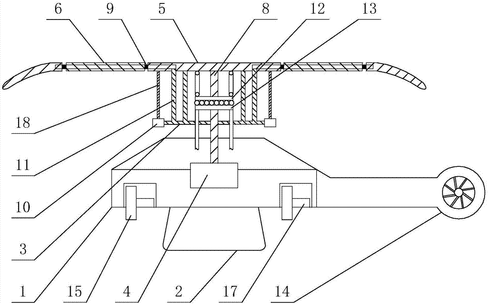
[0033] A dish rotorcraft, such as figure 1 Shown, comprise fuselage 1, rotor system and landing gear 2, described rotor system and landing gear 2 are respectively arranged on the upper and lower parts of fuselage 1, control room and engine 4 are established in fuselage 1, and this aircraft also includes control system ;

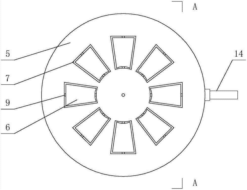
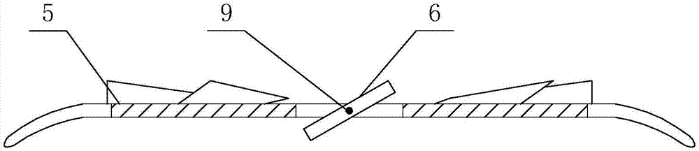
[0034] Such as figure 1 , figure 2 As shown, the rotor system includes a disc rotor 5 and a movable rudder surface 6, the disc rotor 5 is dish-shaped, and its upper surface is uniformly provided with rudder surface openings 7 of the same shape and size as the movable rudder surface 6, The middle part of the bottom surface of the disc rotor 5 is connected to a central shaft 8 in rotation, and the other end of the central shaft 8 is connected to the transmission system of the engine 4. There are 8 movable rudder surfaces, which are respectively embedded in the rudder surface openings 7, and each movable rudder surface 6 The middle part traverses a rotating ...

Embodiment 2

[0042] A dish rotorcraft, its structure is basically the same as that of Embodiment 1, the difference is that there are 2 to 6 movable rudder surfaces, and the corresponding rudder surface control panels are connected to the rotating shaft through 2 to 6 connecting rods, There are 2 ducted propellers, which are located on both sides of the aircraft.

Embodiment 3

[0044] A kind of disc rotorcraft, its structure is basically the same as embodiment one or embodiment two, the difference is that, as Figure 6 As shown, the aircraft also includes a coaxial anti-propeller rotor 19, which replaces the balanced propeller 14 in the above-mentioned embodiment one and embodiment two. The upper part of the rotor 5 constitutes a coaxial anti-paddle type with the disc rotor 5, and the direction of rotation is opposite so as to offset the reaction force produced by the rotation of the disc rotor and stabilize the fuselage.

[0045] Action process:

[0046] ①Take off:

[0047] The engine 4 starts, the central shaft 8 rotates, the disc rotor 5 rotates horizontally, the movable rudder surface 6, the rudder surface control mechanism and the moving disk 12 of the automatic tilter rotate together, the fixed disk 13 is fixed, and the control room issues instructions , the rudder surface drive motor 10 drives the rudder surface control panel 3, so that the ...


PUM


Abstract

The invention relates to a disc type rotor craft. The disc type rotor craft. The disc type rotor craft comprises a body, a rotor system, a landing gear and a control system, wherein the rotor system comprises a disc type rotor and n movable control surfaces, control surface openings are evenly formed in the upper surface of the disc type rotor, the middle of the lower bottom surface of the disc type rotor is connected with an engine transmission system through a central shaft, the movable control surfaces are embedded into the control surface openings, the middle of each movable control surface is movably connected with the disc type rotor through a rotary shaft, and the movable control surfaces can be driven by the rotary shafts to rotate relative to the disc type rotor; the control system comprises an automatic inclinator for controlling the pitching angle of the disc type rotor and a control surface control mechanism for controlling the rotating angles of the movable control surfaces, and the control surface control mechanism comprises a control surface control disc and a control surface drive motor. The rotor craft further comprises a balance propeller and a duct type propeller. The disc type rotor craft which utilizes the aerodynamics feature of the disc type rotor is good in stability, low in power consumption, high in interference resistance, high in cruising ability, convenient to control, high in operability and high in safety.

Description

technical field [0001] The invention relates to the technical field of aviation aircraft, in particular to a dish rotor aircraft. Background technique [0002] There are many types of existing aircraft, including airplanes, helicopters, disc aircraft, rotorcraft, etc., which can be widely used in transportation, patrol, tourism, rescue and other fields, but the aircraft currently in use: [0003] 1. The structure of the propeller aircraft is complex and difficult to control; [0004] 2. Due to the high force requirements of the propeller, the manufacturing materials and processes of the helicopter are complicated, the manufacturing cost is high, and the aerodynamic stability and controllability are poor, and the endurance is weak, resulting in frequent accidents; [0005] 3. The multi-rotor UAV has a complex structure and poor anti-interference ability. Due to the turbulent flow and wingtip stall generated during the propeller movement, it is easy to cause a drop in lift...

Claims


Application Information

Patent Timeline
Patent Type & Authority Applications(China)
IPC IPC(8): B64C27/28B64C9/06B64D17/80
CPCB64C9/06B64C27/28B64D17/80B64U2101/00B64U30/20B64U50/14B64U10/10
Inventor 曾照亮
Owner 东营凯奕科技有限公司
Why Eureka
Try Eureka