
Floating type servo pusher

A floating type, pusher technology, applied in the direction of packaging, etc., can solve the problems of increasing equipment footprint, inconvenient operation for workers, and inability to complete the pushing action stably, and achieve the effect of simple structure and reduced worker participation

Inactive Publication Date: 2017-11-24
泰兴市博越自动化机械制造有限公司
View PDF7 Cites 3 Cited by
  • Summary
  • Abstract
  • Description
  • Claims
  • Application Information

AI Technical Summary

Problems solved by technology

In the prior art, the pushing mechanism adopts a bottom transmission structure, which takes up more space at the bottom of the equipment, increases the floor space of the equipment, is inconvenient for workers to operate, and cannot realize the automation of the pushing action. In addition, the prior art Most of the pushing mechanism still exists in the high-speed working state, and cannot complete the pushing action stably

Method used


Image

  • Floating type servo pusher
  • Floating type servo pusher

Examples


Embodiment Construction

[0011] The following will clearly and completely describe the technical solutions in the embodiments of the present invention with reference to the accompanying drawings in the embodiments of the present invention. Obviously, the described embodiments are only some, not all, embodiments of the present invention. Based on the embodiments of the present invention, all other embodiments obtained by persons of ordinary skill in the art without making creative efforts belong to the protection scope of the present invention.

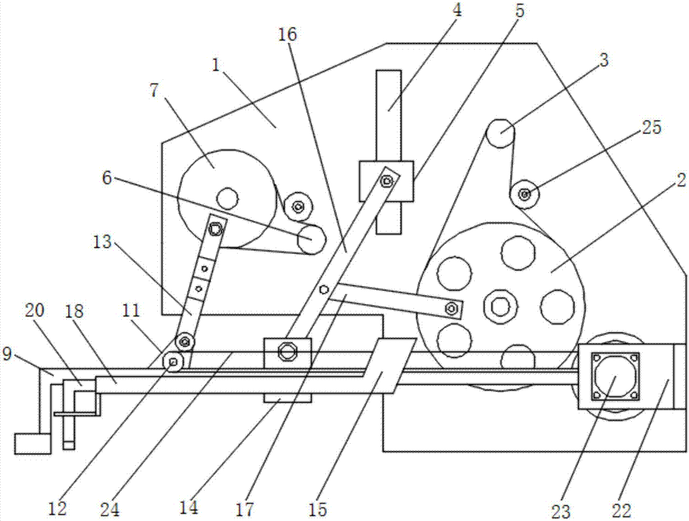
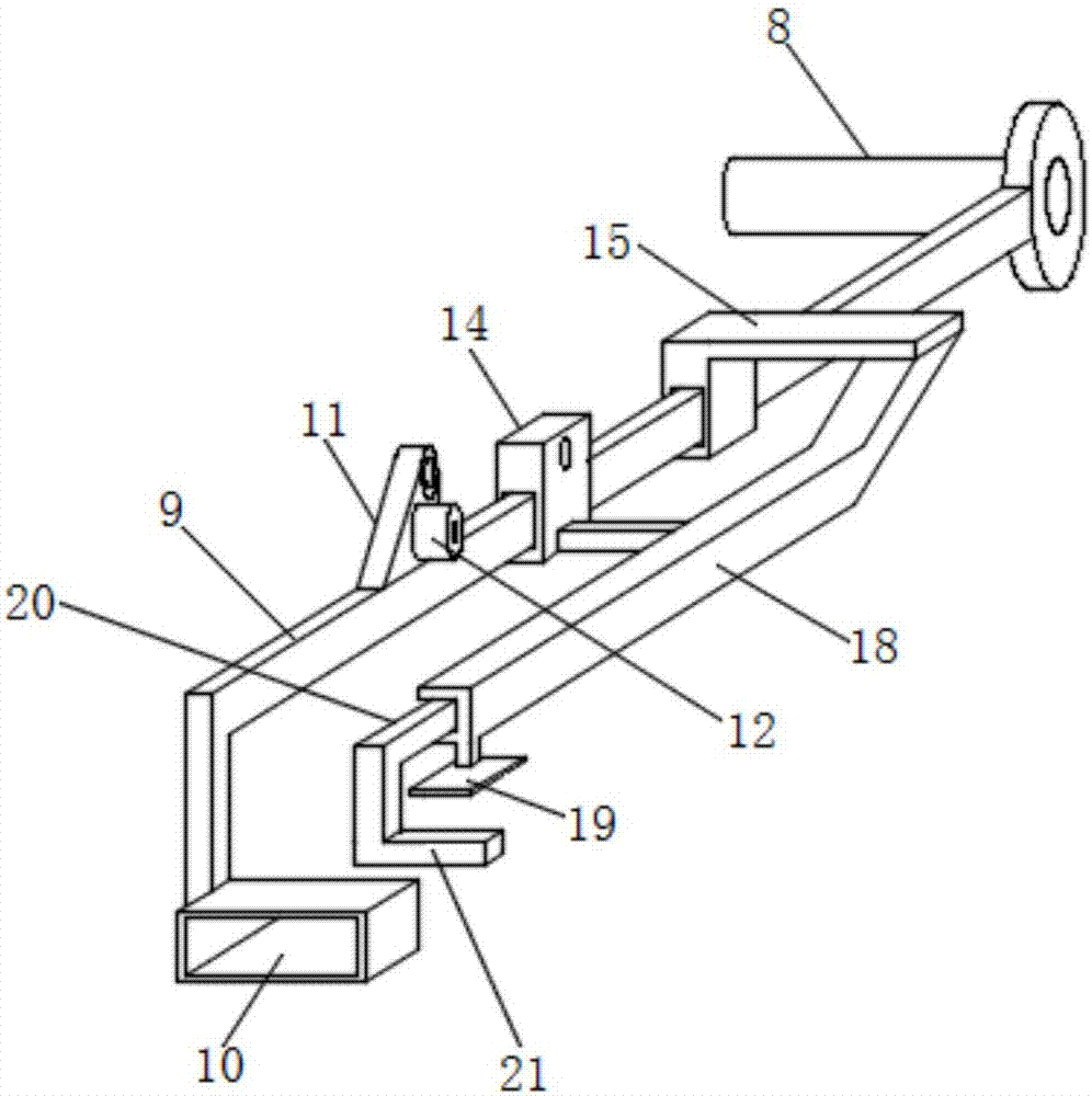
[0012] see Figure 1-2 , the present invention provides a technical solution: a floating servo pusher, including a mounting plate 1, the lower end of the right side of the front surface of the mounting plate is rotatably installed with a pushing pulley 2, and the upper side of the pushing pulley is The surface of the mounting plate runs through and rotates the output end of the pusher servo motor 3, the pusher pulley and the output end of the pusher servo moto...


PUM


Abstract

The invention discloses a floating type servo pusher. The floating type servo pusher comprises a mounting plate, and a material pushing belt pulley is rotatably mounted at the lower end of the right side of the front surface of the mounting plate. The output end of a material pushing servo motor is rotatably mounted in the portion, above the material pushing belt pulley, of the surface of the mounting plate in a penetrating mode. A floating servo motor, a floating belt pulley, a floating swing arm, a connecting block and a rotary shaft are arranged in a matched mode and can enable the left end of a floating lever to regularly conduct actions of ascending and descending. The material pushing servo motor, the material pushing belt pulley, a material pushing connecting rod, a material pushing swing arm and a material pushing sliding block are arranged in a matched mode and can enable a material pushing lever to do reciprocating movement in the direction of the floating lever. A material protection sliding block, a material protection servo motor, a driven belt pulley, a driving belt pulley and a belt are arranged in a matched mode and can enable a material protection lever to do reciprocating movement on the material pushing lever. Through matching of a position frame, a material pushing head and a material pushing plate, articles can be effectively pushed into a box. The floating type servo pusher is simple in structure and capable of conducting automatic operation, reduces participation of workers in the box packing process and can stably complete material pushing operation.

Description

technical field [0001] The invention relates to the technical field of pushing devices, and the specific field is a floating servo pushing device. Background technique [0002] The pushing mechanism is the pushing part on the automatic cartoning machine, the purpose is to push the material into the carton. In the prior art, the pushing mechanism adopts a bottom transmission structure, which takes up more space at the bottom of the equipment, increases the floor space of the equipment, is inconvenient for workers to operate, and cannot realize the automation of the pushing action. In addition, the prior art Most of the pusher mechanisms still exist in high-speed working conditions, and cannot complete the pusher action stably. Contents of the invention [0003] The object of the present invention is to provide a floating servo pusher to solve the problems raised in the background art above. [0004] In order to achieve the above object, the present invention provides the ...

Claims


Application Information

Patent Timeline
Patent Type & Authority Applications(China)
IPC IPC(8): B65B35/40
CPCB65B35/40
Inventor 杨栋梁
Owner 泰兴市博越自动化机械制造有限公司
Learn More