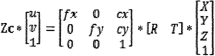
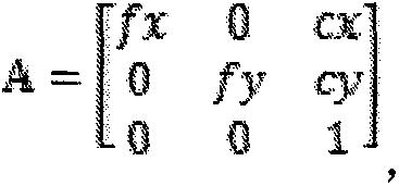
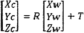
[0029] The present invention will be described in detail below in conjunction with the examples. This technology uses video monitoring technology to form a sequence of images in real time on the flow of the river section, automatically detects and tracks the buoys on the water surface in the sequence images, and uses the principles of solid geometry and photogrammetry to establish a conversion model between the image and the actual water surface coordinates to obtain the buoyancy The time and moving distance of objects moving in the field of view are calculated to obtain the flow velocity of the flood. Place suspended objects as buoys in the river, select the field of view of the camera, and place the camera fixedly for recording. The reality of the present invention mainly includes the following aspects: video-based moving target detection and tracking, camera calibration method and the parameters obtained through the previous steps to solve the water velocity.
[0030] 1. Video-based moving target detection and tracking
[0031] The basic task of moving target detection is to detect the moving target from the sequence images, and obtain the feature information of the moving target, such as color, shape, outline and so on. The process of extracting moving objects is very similar to image segmentation, but image segmentation generally has prior knowledge, and moving objects can only find differences in continuous image sequences, and extract the differences due to object movement. The work of this experiment is mainly to detect the moving target through the frame difference method.
[0032] The inter-frame difference method is a pixel-based motion detection method, which obtains the outline of the moving object by performing differential operations on two or three adjacent images in the video image sequence. The advantage of the frame difference method is that it is only sensitive to moving objects, and because the time interval between the two images is short, the difference image is less affected by changes in ambient light, and the detection is effective and stable.
[0033] During the video-based flood velocity measurement experiment, since the brightness of the environment does not change much in a short time range, and the difference in pixel intensity between two adjacent frames is small, it is considered to be a pixel in the background. If the pixel Regions with large variations in intensity can be assumed to be caused by motion. This method is the most commonly used algorithm in moving target detection. It is characterized by simple implementation, fast calculation speed, good real-time performance, good detection effect in most cases, and is suitable for dynamically changing environments.
[0034] The realization process of frame difference method: Let I k-1 (x, y), I k (x, y), respectively represent the k-1th and k frames in the video image sequence, and the difference between two adjacent frames can be obtained as:
[0035]
[0036] 2. Camera calibration
[0037] Camera calibration comes from photogrammetry. The method used in photogrammetry is a mathematical analysis method. In the calibration process, mathematical methods are usually used to process the data obtained from the image. Through mathematical processing, camera calibration provides the link between non-measurement cameras and professional cameras. The so-called non-measurement cameras refer to cameras whose internal parameters are completely unknown, partially unknown or in principle uncertain. The internal parameters of the camera refer to the basic parameters of camera imaging, such as the principal point (image center), focal length, lens distortion and other parameters. The present invention uses the traditional camera calibration method to solve the internal parameters and external parameters of the camera. The solution process is as follows:
[0038] The relationship between the pixel value (u, v) and the coordinates (x, y) on the image is u=x/dx+u0, and v=y/dy+v0 is expressed as
[0039] u v 1 = 1 / dx 0 u 0 0 1 / dy v 0 0 0 1 x y 1
[0040] The world coordinate system is the coordinate system used to describe the position of the camera in the real world, and it can be used to describe the position of any object in the world environment. He observes the origin and X from the datum w Y w Z w axis composition. The relationship between the camera coordinate system and the world coordinate system can be described by the rotation matrix R and the translation vector t. Therefore, the position of a point p in the air can be expressed in the camera coordinate system as
[0041] Xc Yc Zc = R Xw Yw Zw + T
[0042] Where R is a 3*3 orthogonal rotation matrix and T is a 3*1 translation matrix:
[0043] R = r 1,1 r 1,2 r 1,3 r 2,1 r 2,2 r 2,3 r 3,1 r 3,2 r 3,3 , T = Tx Ty Tz
[0044] Among them, r1, 1-r3, 3 are 9 real parameters which are external parameters of the camera.
[0045]Camera models are mainly divided into linear models and nonlinear models. A linear pinhole model is used in the calibration. In this model, imagine a ray being emitted from a scene or a distant object, but only as a ray from a single point. In a real pinhole camera, this point is "projected" onto the imaging surface. The result is that on the image surface, the image is in focus. The image size relative to distant objects is thus described by only one camera parameter: the focal length. The imaging position of any point P in space on the image can be approximated by the pinhole model, that is, the projected position p of any point P on the image is the intersection of the line OP connecting the optical center O and point P and the image plane. This relationship Also known as central projection or perspective projection. The proportional relationship is as follows:
[0046] x = fXc Zc y = fYc Zc
[0047] Among them, (x, y) is the image coordinate of point p; (Xc, Yc, Zc) is the coordinate of the spatial point P in the camera coordinate system. The relationship between this perspective projection is represented by the secondary coordinates and the matrix, which has the following formula:
[0048] Zc * u v 1 = f 0 0 0 f 0 0 0 1 Xc Yc Zc 1
[0049] Substituting the above two formulas into the above formula, the relationship between the coordinates of point P represented by the world coordinate system and the coordinates (u, v) of point p of the projected point is obtained:
[0050] Zc * u v 1 = fx 0 cx 0 fy cy 0 0 1 * R T * X Y Z 1
[0051] make: A = fx 0 cx 0 fy cy 0 0 1 , A is the internal parameter matrix, the internal parameters include lens focal length, lens distortion parameters
[0052] number, coordinate warping factor, image coordinate origin, etc.
[0053] D=[R T] is the external parameter matrix.
[0054] 3. Solve the water velocity
[0055] Synthesis of camera calibration and object tracking results. The internal and external parameters of the camera can be obtained by camera calibration, and the image coordinates of the buoy in each frame of the image can be obtained by target tracking. According to the camera calibration parameters and the conversion formula between the image coordinates and the midpoint of the world coordinate system, the coordinates of the point in the world coordinate system can be obtained (xn, yn). According to the following formula, it can be concluded that the actual distance that the buoy moves in the world coordinate system is
[0056] s = ( x n - x 1 ) 2 + ( y n - y 1 ) 2
[0057] Among them, (x1, y1) represents the starting position coordinates of the object moving in the monitoring field of view; (xn, yn) represents the ending pixel coordinates of the object leaving the monitoring field of view. According to the formula, the surface water velocity V of the river is equal to:
[0058] v = S 1 / F
[0059] Among them, F is the frame rate of the video.