Eureka AIR delivers breakthrough ideas for toughest innovation challenges, trusted by R&D personnel around the world.

Crane jib breakage and falling safety protection device

A technology of safety protection device and boom, which is applied in the direction of cranes, etc., can solve the safety hazards of on-site construction personnel, casualties, damage and other problems, and achieve the effect of reducing casualties and property losses, ensuring normal operation, and ensuring safety

Active Publication Date: 2017-11-24
江苏省海通索具有限公司
View PDF7 Cites 0 Cited by
  • Summary
  • Abstract
  • Description
  • Claims
  • Application Information

AI Technical Summary

Problems solved by technology

[0002] In the field of lifting equipment, some large-scale lifting machinery such as tower cranes, bridge cranes, truck-mounted cranes, etc., all need to use booms to complete the lifting and transfer of heavy objects. It is more and more popular among people; however, in recent years, accidents of breaking the boom of the truck-mounted crane have occurred frequently, and the broken boom will fall, and because the boom itself is heavy and the working position is high, when the crane When the arm falls to the ground or platform, it is very easy to cause casualties to varying degrees and damage to vehicles and equipment on the construction site, which brings a lot of unnecessary troubles and property losses to the project construction, especially in some serious accidents. The number of casualties is often large, so the truck-mounted crane poses a great safety threat to the on-site construction personnel during the operation

Method used


Image

  • Crane jib breakage and falling safety protection device
  • Crane jib breakage and falling safety protection device
  • Crane jib breakage and falling safety protection device

Examples


Embodiment Construction

[0014] The specific implementation manners of the present invention will be described in further detail below in conjunction with the accompanying drawings.

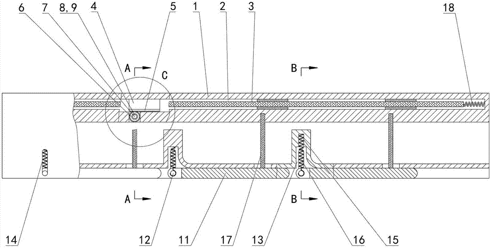
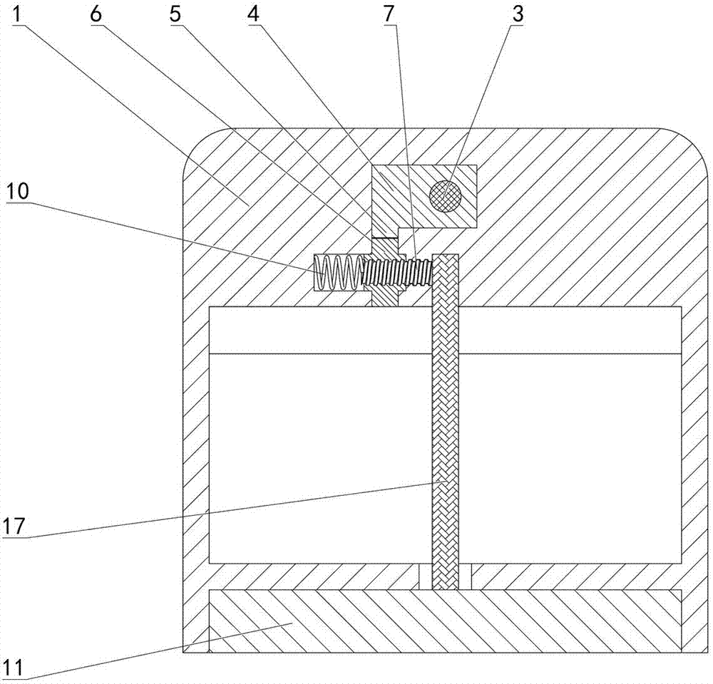
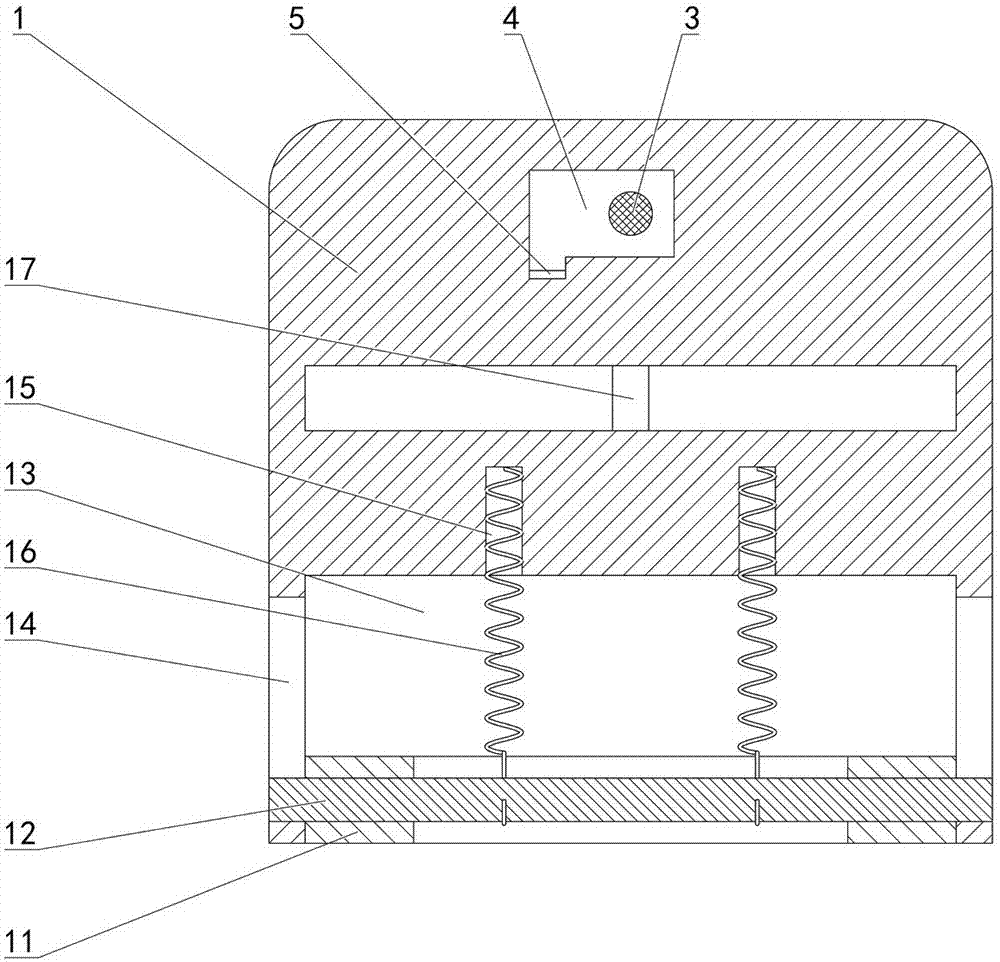
[0015] Depend on Figure 1 to Figure 5 Given, the present invention comprises the boom 1 that is horizontally arranged, the boom 1 is provided with the chute 2 consistent with the length direction of the boom 1, the steel wire rope 3 consistent with the length direction of the boom 1 is arranged in the chute 2, and the steel wire rope 3 The right end is connected with the boom 1, the steel wire rope 3 is equipped with a plurality of sliders 4 that can slide left and right in the chute 2, the slider 4 is equipped with a rack 5 placed below the slider 4, and the length direction of the rack 5 is in line with the The length direction of the boom 1 is consistent, the boom 1 is equipped with a gear 6 meshing with the rack 5, the gear 6 is placed under the rack 5, and the gear 6 is equipped with a screw 7 coaxially arranged wi...


PUM


Abstract

The invention relates to a crane jib breakage and falling safety protection device, which comprises a jib. The jib has a chute, inside which a wire rope is arranged. The right end of the wire rope is connected to the jib. Multiple slide blocks which can slide in the chute are arranged on the wire rope. Each slide block is equipped with a gear rack; a gear which is engaged with the gear rack is arranged on the jib; a screw which can coaxially slide with the gear is arranged on the gear; and the screw is in threaded connection with the jib. Torsion springs are arranged on the jib. Two ends of each torsion spring are respectively connected to the jib and the corresponding gear. The jib has multiple support frames which are arranged below the jib. The left end of each support frame is hinged to the jib through a rotating shaft. Multiple demising grooves are arranged at the lower end face of the jib. Front and rear end faces of each demising groove are respectively provided with a vertical chute. Two ends of the rotating shaft are respectively placed inside the vertical chute. The bottom of the demising groove is provided with a counter bore, inside which an extension spring is arranged. The upper end of the extension spring is fixed inside the counter bore, and the lower end of the extension spring is connected to the rotating shaft. There is a safety rope on the support frame, and one end of the safety rope vertically passes through the jib and is extruded on the jib through the rear end of the screw.

Description

technical field [0001] The invention relates to the technical field of lifting equipment, in particular to a safety protection device for breaking and falling of a lifting arm. Background technique [0002] In the field of lifting equipment, some large-scale lifting machinery, such as tower cranes, bridge cranes, and truck-mounted cranes, all need to use booms to complete the lifting and transfer of heavy objects. It is more and more favored by people; however, in recent years, accidents of breaking the boom of the truck-mounted crane have occurred from time to time, and the broken boom will fall, and because the boom itself is heavy and the working position is high, when the crane When the arm falls to the ground or platform, it is very easy to cause casualties to varying degrees and damage to vehicles and equipment on the construction site, which brings a lot of unnecessary troubles and property losses to the project construction, especially in some serious accidents. The...

Claims


Application Information

Patent Timeline
Patent Type & Authority Applications(China)
IPC IPC(8): B66C23/88B66C23/64
CPCB66C23/64B66C23/88
Inventor 陆成帅
Owner 江苏省海通索具有限公司
Why Eureka
Eureka Blog
Learn More