
Gear Pump

A gear pump and gear technology, applied in the direction of pumps, pump components, rotary piston pumps, etc., can solve the problems of unstable pump performance and reduced flow rate.

Inactive Publication Date: 2017-11-28
JTEKT CORP
View PDF1 Cites 0 Cited by
  • Summary
  • Abstract
  • Description
  • Claims
  • Application Information

AI Technical Summary

Problems solved by technology

Therefore, the flow rate decreases, etc., and the pump performance becomes unstable.

Method used


Image

  • Gear Pump
  • Gear Pump
  • Gear Pump

Examples


Embodiment 1

[0063] The amount of deviation ΔYa in the orthogonal direction V in Example 1 is much smaller than the amount ΔYc in the orthogonal direction V in Example 2 (ΔYa<ΔYc). Therefore, in Example 1, compared with Example 2, it is considered that due to the deviation of the dimensional tolerance of each component, even if the position of the second contact point P2 is deviated along the circumferential direction of the cylindrical holes 21 and 22, The variation in the position of the second contact point P2 in the orthogonal direction V can be further suppressed to be smaller, and the variation in performance can be further suppressed.

[0064] The present invention is not limited to the above-mentioned embodiment, although it is not shown in the figure, it can also be from any position, for example, as Figure 5A As shown, from the position of the second contact point P2 such that the first straight line L1 is perpendicular to the second straight line L2, the side having the second ...


PUM


Abstract

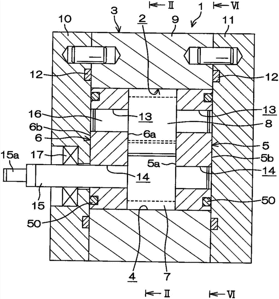
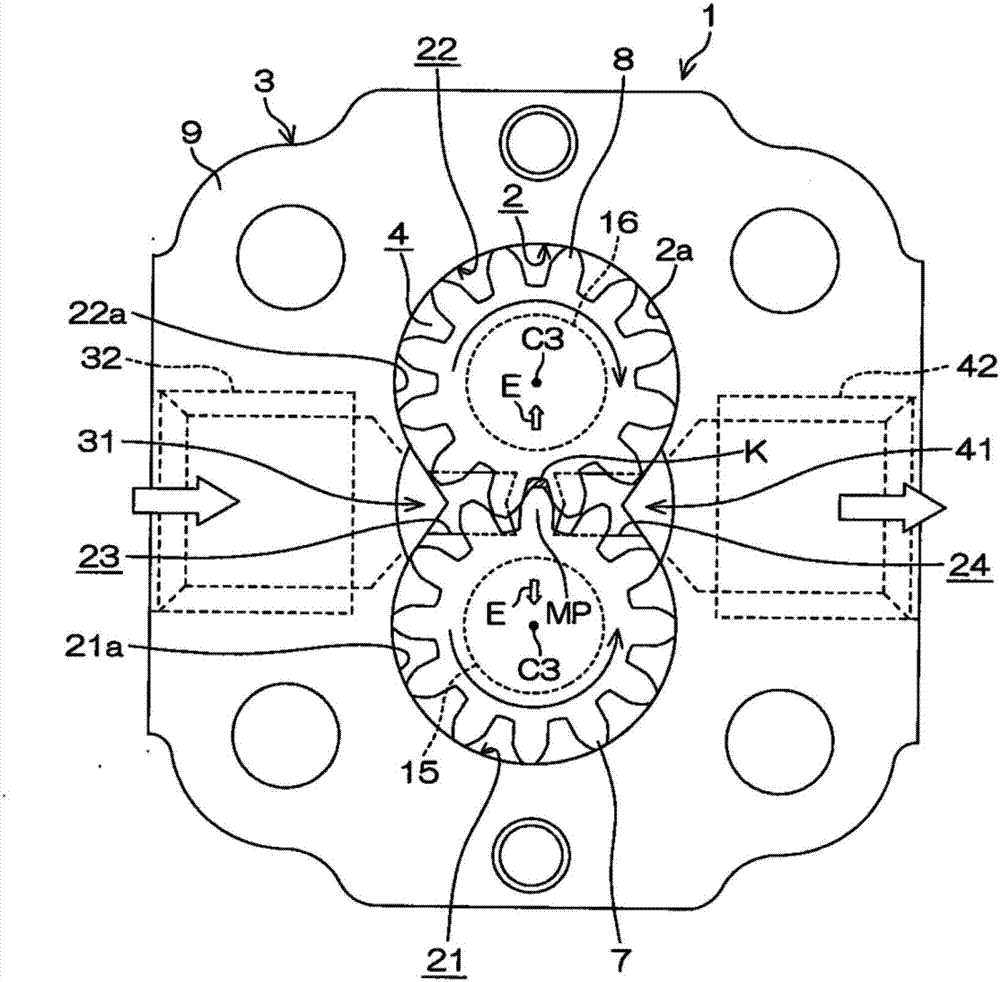
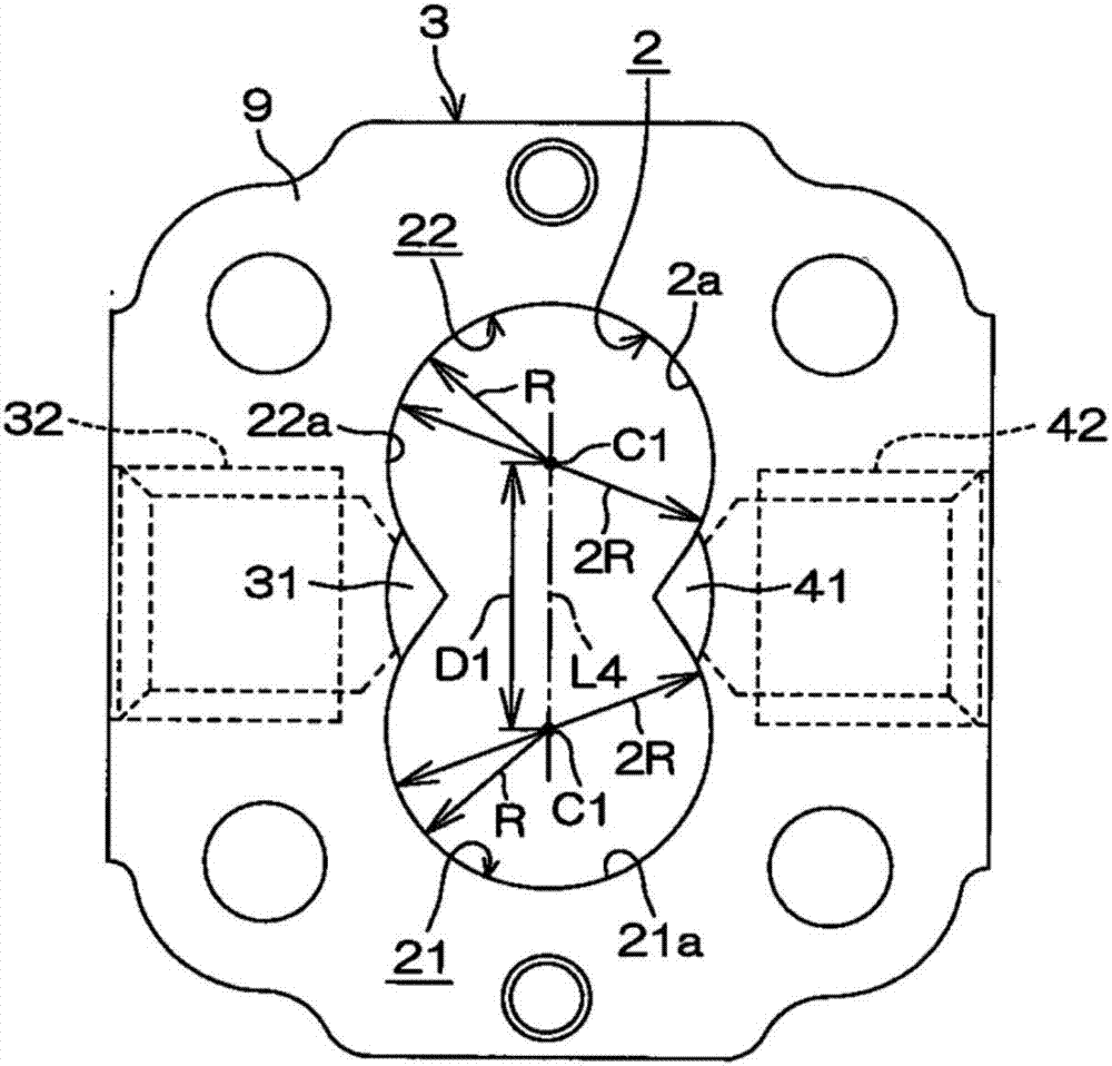
In a gear pump, a gear chamber is defined in a housing hole of a housing. A pair of gears is housed in the gear chamber. The gears are rotatably supported at support holes of a pair of side plates via support shafts. As viewed in an axial direction of the support shafts during rotation of the gears, addendum circles of the gears displaced under a differential pressure between a low-pressure chamber and a high-pressure chamber form first contact points with respect to an inner peripheral surface that defines a housing hole. As viewed in the axial direction of the support shafts during rotation of the gears, the first contact points are covered with the side plates displaced under the differential pressure.

Description

technical field [0001] The present invention relates to gear pumps. Background technique [0002] The structure of a common gear pump is as follows: a pair of gears meshing with each other is accommodated in the housing, and a pair of side plates arranged across the pair of gears in the axial direction are used to divide and form a gear chamber in the housing hole. The support holes of the side plates rotatably support the support shafts of the respective gears. For example, refer to Japanese Patent Application Laid-Open No. 10-122160. [0003] When the gear pump is viewed from the axial direction of the gear, a low-pressure chamber communicating with the suction port of the working fluid and a high-pressure chamber communicating with the discharge port of the working fluid are disposed inside the gear chamber with the meshing position of the two gears interposed therebetween. room. Each side plate is arranged with clearance fit relative to the receiving hole. [0004] I...

Claims


Application Information

Patent Timeline
Patent Type & Authority Applications(China)
IPC IPC(8): F04C2/18
CPCF04C2/18F04C15/0046F04C2240/50F04C2/14F04C15/0049F04C15/06F04C18/14F04C29/0035F04C29/12F04C2240/30F04C2240/60
Inventor 吉田直史
Owner JTEKT CORP
Learn More