Anti-loose type equipment clamp

A technology of clamping and anti-loosening of equipment, applied in the direction of clamping/spring connection, multi-conductor connectors, electrical components, etc., can solve the problems of small conductive contact area, current overload, easy loosening, etc., and achieve large conductive contact area, Easy to install or disassemble, and avoid the effect of copper-aluminum transition problem

Active Publication Date: 2017-11-28
GUANGZHOU PANYU CABLE WORKS
View PDF11 Cites 6 Cited by
  • Summary
  • Abstract
  • Description
  • Claims
  • Application Information

AI Technical Summary

Problems solved by technology

[0002] The equipment clamp is used for the conductive connection between the equipment terminal and the cable terminal of the electrical equipment. The current equipment clamp usually uses bolts to directly connect the equipment terminal and the cable terminal equipped with the terminal. This connection method is easy There are the following problems: the conductive contact area between the equipment terminal and the wiring terminal is small, the bolt stress easily causes the contact surface between the equipment terminal and the wiring terminal to deform and produce a gap, and it is easy to loosen after a long time. These problems will lead to poor contact between the equipment terminal and the wiring terminal , the interface interface resistance is large, and the temperature rise is large, which will lead to current overload operation and bring hidden dangers to electricity safety

Method used


Image

  • Anti-loose type equipment clamp
  • Anti-loose type equipment clamp
  • Anti-loose type equipment clamp

Examples


Embodiment Construction

[0026] In order to make the object, technical solution and advantages of the present invention clearer, the present invention will be further described in detail below in conjunction with the accompanying drawings and embodiments. It should be understood that the specific embodiments described here are only used to explain the present invention, not to limit the present invention.

[0027] It should be noted that the "first" and "second" herein are only used for the description purpose of distinction, and should not be understood as indicating or implying the quantity or sequence of technical features.

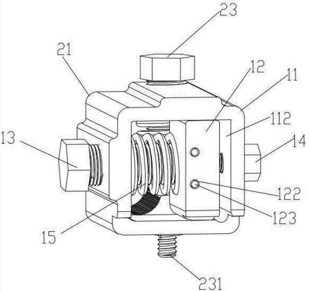
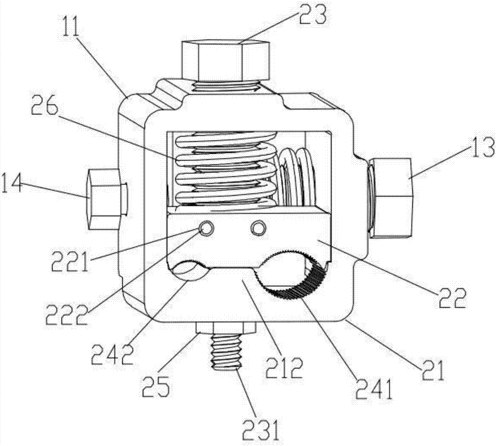
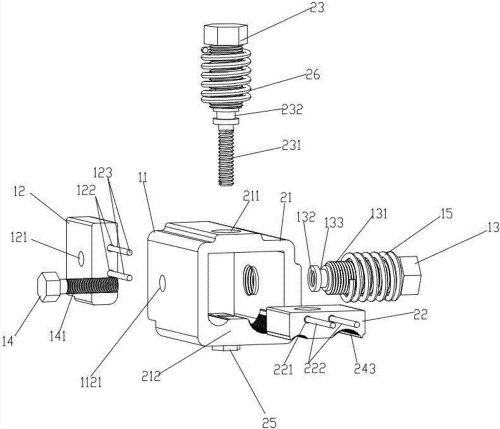
[0028] Such as Figure 1-8 As shown, an anti-loosening equipment clamp includes equipment clamps for connecting equipment terminals and cable clamps for connecting cable terminals. The equipment clamps include equipment clamp body 11, dynamic pressure plate 12, fastening bolts 13 and Anti-loosening bolt 14, the outer surface of fastening bolt 13 is provided with positive exte...


PUM


Abstract

The present invention relates to the technical field of the equipment clamp, in particular to an anti-loose type equipment clamp. The anti-loose type equipment clamp comprises an equipment clamp and a cable clamp. The equipment clamp comprises an equipment clamp body, a dynamic pressure plate, a fastening bolt and a check bolt; the fastening bolt is also provided a reverse internal thread hole; the check bolt is provided with a reverse external thread; the equipment clamp body is provided with a fastening thread hole and a static pressure plate that are arranged opposite to each other; the fastening bolt passes through the fastening thread hole and is rotatably connected with the dynamic pressure plate; and the check bolt is inserted into the fastening bolt and connected with the reverse thread of the fastening bolt. The cable clamp comprises a cable clamp body, a dynamic clamp head and a locking bolt; the cable clamp body is provided with a locking thread hole and a static clamp head that are arranged opposite to each other; the locking bolt passes through the locking thread hole and is rotatably connected with the movable clamp head; and the dynamic clamp head and the static clamp head are provided with pressure grooves. Beneficial effects of the loose type equipment clamp provided by the present invention are that the conductive contact area between the equipment terminal and the equipment clamp is large, installation is firm, the contact surface is hard to generate a gap, and the safety and reliability are ensured.

Description

technical field [0001] The invention relates to the technical field of equipment wire clips, in particular to an anti-loosening type equipment wire clip. Background technique [0002] The equipment clamp is used for the conductive connection between the equipment terminal and the cable terminal of the electrical equipment. The current equipment clamp usually uses bolts to directly connect the equipment terminal and the cable terminal equipped with the terminal. This connection method is easy There are the following problems: the conductive contact area between the equipment terminal and the wiring terminal is small, the bolt stress easily causes the contact surface between the equipment terminal and the wiring terminal to deform and produce a gap, and it is easy to loosen after a long time. These problems will lead to poor contact between the equipment terminal and the wiring terminal , The interface interface resistance is large, and the temperature rise is large, which wil...

Claims


Application Information

Patent Timeline
Patent Type & Authority Applications(China)
IPC IPC(8): H01R11/01H01R11/03H01R4/40H01R4/42
CPCH01R4/40H01R4/42H01R11/01H01R11/03
Inventor 胡超强尤占山孙建吉覃丹陈雪儿卢广业张开拓王延发张仕欢郝燕邵源鹏程雪丽刘金勇
Owner GUANGZHOU PANYU CABLE WORKS
Why Eureka
Try Eureka