
Monitoring device, monitoring system and monitoring method for power transmission line

A technology of transmission lines and monitoring devices, applied in the field of electric power, can solve the problems of indirect data and the inability to collect real-time data of galloping transmission wires, etc., and achieve the effect of improving accuracy

Pending Publication Date: 2017-11-28
BEIJING GUOWANG FUDA SCI & TECH DEV +1
View PDF5 Cites 4 Cited by
  • Summary
  • Abstract
  • Description
  • Claims
  • Application Information

AI Technical Summary

Problems solved by technology

[0007] The embodiment of the present invention provides a monitoring device for power transmission lines to solve the technical problem that the real-time data of the galloping of the power transmission wires cannot be collected in the prior art, and only indirect data is collected
[0008] The embodiment of the present invention also provides a monitoring system for transmission lines to solve the technical problem in the prior art that the real-time data of the galloping of the transmission wires cannot be collected and only indirect data is collected

Method used


Image

  • Monitoring device, monitoring system and monitoring method for power transmission line
  • Monitoring device, monitoring system and monitoring method for power transmission line
  • Monitoring device, monitoring system and monitoring method for power transmission line

Examples


Embodiment Construction

[0028] In order to make the object, technical solution and advantages of the present invention clearer, the present invention will be described in further detail below in conjunction with the embodiments and accompanying drawings. Here, the exemplary embodiments and descriptions of the present invention are used to explain the present invention, but not to limit the present invention.

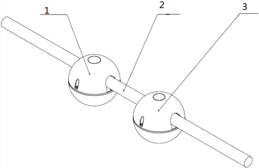
[0029] In an embodiment of the present invention, a monitoring device for a power transmission line is provided, such as figure 1 As shown, the device includes:

[0030] The monitoring terminal 1 is installed on the power transmission line 2 to be monitored, and is used to obtain the spatial position information of the power transmission line to be monitored from the satellite in real time, wherein the real-time acquired spatial position information of the power transmission line to be monitored is to generate the The basis for the galloping trajectory of the transmission conductor to be monit...


PUM


Abstract

An embodiment of the invention provides a monitoring device, a monitoring system and a monitoring method for a power transmission line, wherein the monitoring device comprises a monitoring terminal which is mounted on a to-be-monitored power transmission lead and is used for acquiring spatial position information of the to-be-monitored power transmission lead from a satellite in real time, wherein the real-time acquired spatial position information of the to-be-monitored power transmission lead is a basis for generating the motion track of the to-be-monitored power transmission lead. According to the monitoring device, the monitoring system and the monitoring method, because a fact that whether spatial position information occurs can directly reflect whether motion of the to-be-monitored power transmission lead in real time, Furthermore the motion track can more directly and truly reflect the real-time motion condition of the to-be-monitored power transmission lead.

Description

technical field [0001] The invention relates to the field of electric power technology, in particular to a monitoring device, system and method for power transmission lines. Background technique [0002] While my country's power grid is developing rapidly with the growth of the national economy, it is also frequently harassed by meteorological disasters. Ice galloping of overhead conductors is a form of disaster with high frequency, wide range of influence and great loss. In terms of research on dance, we started late and lacked unified deployment. Each unit fought individually, failed to form a joint force, and was inefficient. On January 20, February 28, 2010, and February 27, 2011, Shandong Power Grid encountered large-scale transmission line galloping three times within two years. The conductor galloping caused multiple conductor burns or broken strands, and conductor spacers fell off. Or damage, loose bolts, broken hardware, and broken protective caps on the base of i...

Claims


Application Information

Patent Timeline
Patent Type & Authority Applications(China)
IPC IPC(8): H02J13/00G01D21/02
CPCH02J13/00G01D21/02Y04S40/126Y02E60/00
Inventor 郎庆凯于洪亮林世忠郑鹏超徐方林高方玉张振威倪康婷于钦刚李睿赵坚钧王威高安结
Owner BEIJING GUOWANG FUDA SCI & TECH DEV
Learn More