Air volume distribution structure for rail vehicle air supply passage

A rail vehicle and air supply duct technology, which is applied in the field of air volume distribution structures for rail vehicle air supply ducts, can solve the problem that the rail vehicle air duct cannot be turbulent and muffled, and achieve the effects of avoiding eddy currents and reducing interior noise.

Active Publication Date: 2017-12-01
CRRC NANJING PUZHEN CO LTD
View PDF5 Cites 10 Cited by
  • Summary
  • Abstract
  • Description
  • Claims
  • Application Information

AI Technical Summary

Problems solved by technology

[0006] In view of the above situation, the present invention designs a kind of air volume distribution structure for rail vehicle air supply duct, which solves the defect that the rail vehicle air duct cannot be turbulent and muffled. The specific structure is as follows:

Method used


Image

  • Air volume distribution structure for rail vehicle air supply passage
  • Air volume distribution structure for rail vehicle air supply passage
  • Air volume distribution structure for rail vehicle air supply passage

Examples


Embodiment 1

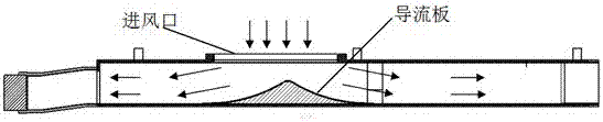
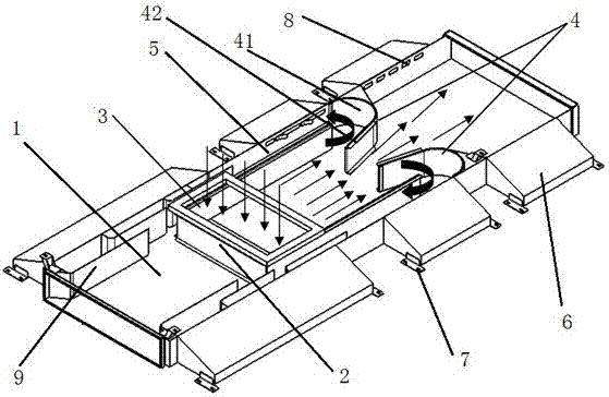
[0023] Such as image 3 As shown, the air volume distribution structure for the air supply channel of a rail vehicle includes a main air channel, and a plurality of air outlets are respectively arranged on both sides of the main air channel 1, and a horizontally arranged U Type plate 2, the upper and lower ends of the U-shaped plate 2 are respectively attached to the top and bottom pipe walls of the main air duct 1, the open end of the U-shaped plate 2 faces one end of the main air duct 1, and the two sides of the U-shaped plate 2 A side air duct 5 is formed between the main air duct 1 and the main air duct 1 is located on the top of the closed end of the U-shaped plate 2 with an air inlet 3, and the main air duct 1 is located in front of the opening end of the U-shaped plate 2. Two The deflectors 4 are symmetrically arranged, and the two deflectors 4 are respectively corresponding to the two side plates of the U-shaped plate 2. There is a gap between the two deflectors 4, and...

Embodiment 2

[0025] In order not to affect the air flow of the main air duct located at the rear of the U-shaped plate, the structure of the main air duct located at the rear of the U-shaped plate is improved. The specific structure is as follows:

[0026] The main air duct 1 is located at the rear of the closed end of the U-shaped plate 2 and is provided with two baffles 9 respectively aligned with the side panels on both sides of the U-shaped plate 2. Set the opening. After the air flow is guided to the side air duct 5 through the deflector 4, part of the air flow is discharged through the air outlet, but because the gas contained in the side air duct 5 is limited, and the exhausted air flow cannot keep up with the imported air flow, so through the A baffle 9 is provided at the rear of the side air duct, so that the airflow flows out from the branch air duct at the position of the baffle, and passes through the opening, and the excess air flows back to the opening position and enters the...

Embodiment 3

[0028] In order to ensure the effect of deflecting the air flow of the deflector, the structure of the deflector is further limited, and the specific structure is as follows:

[0029] The two deflectors 4 are respectively symmetrically installed on the side walls of the corresponding main air duct 1. The end faces of the deflectors 4 facing the side plates are arc-shaped concave surfaces 41, and the arc-shaped surfaces of the two deflectors 4 are The ends of the concave surface 41 are respectively provided with drain plates 42 extending toward the middle of the U-shaped plate 2, and the two drain plates 42 form a gap in a trumpet-shaped structure. The angle range is 30~40°, and the trumpet-shaped structure is used to divert air flow and adjust the forward and return air volume.


PUM


Abstract

The invention discloses an air volume distribution structure for a rail vehicle air supply passage. The air volume distribution structure comprises a main air passage, the two sides of the main air passage are each provided with a plurality of air outlets, and a horizontally-arranged U-shaped plate is arranged in the main air passage. The upper end and the lower end of the U-shaped plate are attached to the pipe walls of the top and the bottom of the main air passage correspondingly, the opening end face of the U-shaped plate points to one end of the main air passage, each of the two sides of the U-shaped plate and the main air passage constitute a side air passage, and an air inlet is formed in the top, located at the closed end of the U-shaped plate, of the main air passage. Two symmetrically-arranged flow guiding plates are arranged on the position, located in front of the opening end of the U-shaped plate, of the main air passage and correspond to two side plates of the U-shaped plate correspondingly. A notch is formed between the two flow guiding plates, and an air flow in the U-shaped plate is distributed to flow into the side air passages of the two sides and the main air passage behind the flow guiding plates, through the two flow guiding plates and the notch between the flow guiding plates. According to the air volume distribution structure for the rail vehicle air supply passages, through the passages formed by the U-shaped plate and the main air passage, the strong air flow entering from an air inlet is buffered, and through flow distribution of the flow guiding plates, noise of the air flow is further reduced.

Description

technical field [0001] The invention relates to an air duct structure, in particular to an air volume distribution structure for an air supply duct of a rail vehicle used on a rail vehicle and connected to an air outlet of an air conditioner unit of the rail vehicle. Background technique [0002] Rail vehicles usually arrange the air-conditioning unit on the top of the vehicle, and the design of the unit is usually in the down-send and down-return mode. For vehicles with limited roof space, the design of the air-conditioning unit also has certain limitations due to the small roof space. In order to provide passengers with a more comfortable and quiet environment, the design of the air duct is particularly important. [0003] Usually, the air sent by the air conditioning unit enters the air duct for distribution. Because the air flow sent by the unit fan is turbulent and turbulent, the design of the air duct connected to the unit should consider both the diversion of the air ...

Claims


Application Information

Patent Timeline
Patent Type & Authority Applications(China)
IPC IPC(8): B61D27/00
CPCB61D27/0018
Inventor 宁宝焕韩昌研龚继如王业蔡瑞晶
Owner CRRC NANJING PUZHEN CO LTD
Why Eureka
Try Eureka