LED lamp device

A technology of LED light device and LED light board, which is applied in the field of lighting, can solve the problems of waste of power resources, reduced service life, long power supply connection lines, etc., and achieve the effects of saving electricity, reducing the risk of damage, and reducing waste

Inactive Publication Date: 2017-12-01
广州弘唷网络科技有限公司
View PDF0 Cites 2 Cited by
  • Summary
  • Abstract
  • Description
  • Claims
  • Application Information

AI Technical Summary

Problems solved by technology

[0002] In the actual construction of the construction site, due to the tight schedule or construction needs, construction needs to be carried out at night, so the lighting on the construction site has become an indispensable tool in the construction process. However, due to the long power supply connection required in the construction lighting process , making it extremely difficult to take in and out the wires, increasing the labor load and reducing work efficiency. At the same time, in the non-use state, the power supply wires are exposed to the outside world for a long time and are vulnerable to various accidental damages, resulting in a decrease in service life. In addition, the existing construction LED lamps all work by connecting to the mains, resulting in waste of power resources, which has major disadvantages and needs to be improved.

Method used


Image

  • LED lamp device
  • LED lamp device
  • LED lamp device

Examples


Embodiment Construction

[0022] All the features disclosed in this specification, or all disclosed methods or steps in the process, except for mutually exclusive features and / or steps, can be combined in any manner.

[0023] Any feature disclosed in this specification (including any appended claims, abstract and drawings), unless specifically stated, can be replaced by other equivalent or equivalent alternative features. That is, unless otherwise stated, each feature is just one example of a series of equivalent or similar features.

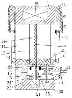
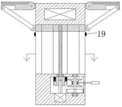
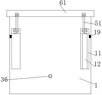
[0024] Such as Figure 1-5 As shown, an LED lamp device of the present invention includes a box body 1 and a current collection mechanism. The bottom of the box body 1 is provided with a manipulation cavity 15, and the bottom wall of the manipulation cavity 15 is fixedly installed with an electric converter 21, so An adapter shaft 22 is fixedly arranged on the top of the electric transfer machine 21, a connecting sleeve 23 is slidably installed on the adapter shaft 21, a gea...


PUM


Abstract

An LED lamp device comprises a box body and a current collection mechanism. A manipulating cavity is formed in the bottom of the box body. An electric rotating machine is fixedly mounted in the bottom wall of the manipulating cavity. An adapting shaft is fixedly arranged on the top of the electric rotating machine. A connecting sleeve is mounted on the adapting shaft in a slidable connection mode. A tooth connection wheel is fixedly mounted on the connecting sleeve. A tooth connecting disc in tooth connection with the tooth connection wheel is mounted in the manipulating cavity through a cable winding rod. A cable winding disc is further fixedly mounted on the cable winding rod. A cable is mounted on the cable winding disc and arranged at a through opening in the side wall of the manipulating cavity in a penetrating mode and extends outwards, and an LED lamp plate is fixedly arranged at the tail end of the cable. Multiple sets of bulbs are arranged in the bottom of the LED lamp plate at equal intervals. A transparent adhesive plate is fixedly arranged on the bottom end face, on the outer sides of the LED bulbs, of the LED lamp plate. The current collection mechanism comprises mounting connection plates and photovoltaic panels, wherein the mounting connection plates are rotatably mounted at the upper ends of the two side walls of the box body in a bilateral-symmetry mode, and the photovoltaic panels are fixedly mounted in the mounting connection plates. An accumulator in electric connection with the photovoltaic panels and the cable, and a pushing-up part are further arranged in the box body.

Description

Technical field [0001] The present invention relates to the field of lighting technology, in particular to an LED lamp device. Background technique [0002] In the actual construction of the construction site, due to the tight schedule or construction needs, construction needs to be carried out at night, so the lighting on the construction site becomes an indispensable tool in the construction process, but the power supply connection line required during the construction lighting process is long , It is extremely difficult to take up and unwind the line, increase labor and reduce work efficiency. At the same time, when the power line is not in use, the power line is exposed to the outside for a long time and is easily damaged by various accidents, resulting in a decrease in service life. In addition, the existing construction uses LED lights all work by connecting to the mains, causing a waste of power resources, which has major drawbacks and needs to be improved. Summary of the...

Claims


Application Information

Patent Timeline
Patent Type & Authority Applications(China)
IPC IPC(8): F21S9/03F21V19/00F21V23/00H02S20/30F21Y115/10
CPCF21S9/03F21V19/003F21V23/002H02S20/30Y02E10/50
Inventor 覃日雄
Owner 广州弘唷网络科技有限公司
Why Eureka
Try Eureka